Download
1 / 24
240 likes | 368 Views
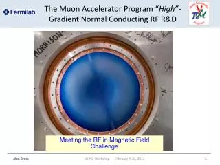
Lecture 8 Normal conducting RF. Copper Cavities. In copper cavities the shunt impedance, R, should be maximised in order to achieve a high accelerating gradient. Normal conducting cavities require nosecones and a small beam pipe in order to increase the shunt impedance factor. Average Heating.

E N D
Copper Cavities In copper cavities the shunt impedance, R, should be maximised in order to achieve a high accelerating gradient. Normal conducting cavities require nosecones and a small beam pipe in order to increase the shunt impedance factor
Average Heating • For CW cavities, the cavity temperature reaches steady state when the water cooling removes as much power as is deposited in the RF structure. • Temperature rises can cause surface deformation, surface cracking, outgassing or even melting. • By pulsing the RF we can reach much higher gradients as the average power flow is much less than the peak power flow.
Pulsed Heating Pulsed RF however has problems due to heat diffusion effects. Over short timescales (<10ms) the heat doesn’t diffuse far enough into the material to reach the water cooling. This means that all the heat is deposited in a small volume with no cooling. Cyclic heating can lead to surface damage.
Field Enhancement • The surface of an accelerating structure will have a number of imperfections at the surface caused by grain boundaries, scratches, bumps etc. • As the surface is an equipotential the electric fields at these small imperfections can be greatly enhanced. • In some cases the field can be increase by a factor of several hundred. Elocal=b E0 2b h
Field Emission • As we saw in Lecture 3, high electric fields can lead to electrons quantum tunnelling out of the structure creating a field emitted current. Once emitted this field emitted current can interact with the cavity fields. Although initially low energy, the electrons can potentially be accelerated to close to the speed of light with the main electron beam, if the fields are high enough. This is known as dark current trapping.
Breakdown • Breakdown occurs when a plasma discharge is generated in the cavity. • This is almost always associated with some of the cavity walls being heated until it vaporises and the gas is then ionised by field emission. The exact mechanisms are still not well understood. • When this occurs all the incoming RF is reflected back up the coupler. • This is the major limitation to gradient in most pulsed RF cavities and can permanently damage the structure.
Maximum Gradient Limits • All the limiting factors scale differently with frequency. • They also mostly vary with pulse length. • The limiting factor tends to be different from cavity to cavity.
RF Conditioning • As a cavity is often manufactured with a number of nucleation sites for breakdown it is necessary to condition the cavity. • This consists of a number of semi-controlled RF breakdowns, caused by increasing the RF power very slowly over a number of days/hours. • This causes vaporisation of the nucleation sites just above the breakdown threshold causing a minimum amount of damage.
Nose Cones If we decrease the accelerating gap, while keeping the same voltage between the gap, the effective accelerating voltage increases due to the transit time factor. As the gap is smaller the field strengths increase, which is good where the beam is but bad elsewhere. To avoid problems we only decrease the gap near the beam. The narrowed gap region is known as a nose-cone.
RFQ Radio frequency Quadropoles are electrostatic quad’s for focussing the beam. If the electrodes are specially spaced they can also accelerate the beam. This is especially useful for low energy beams where space charge forces are large.
Side coupled cavities • For multicell cavities a small aperture leads to low coupling between the cavities. • This causes there to be very small frequency separation between modes. • In order to increase the cell-to-cell coupling we can use a side cavity. • We then use a p/2 mode, where the side cell has low fields.
Standing Wave Cavities The most common type of structure is the p mode standing wave structure. This can be a single cell or multiple cells coupled together. These structures cannot have too many cells per cavity and means that for high energy accelerators many couplers are required. The cost of this is why these structures are overlooked for linear colliders like CLIC and NLC.
Travelling wave structures • Normal conducting cavities can be standing wave or travelling wave. • If a standing wave cavity is similar to a klystron (in reverse), then travelling wave structures are similar to TWTs. • In TW structures the waves phase velocity, is equal to the speed of the particles to be accelerated. • Power can flow through all the cavities, very low Q.
Phase Advance • Not all cells in a multi-cell structure will have the same phase. • The phase difference between two cells is known as the phase advance. • In a travelling wave structure the phase advance is the axial wavenumber multiplied by the iris spacing (f=kzL) • An iris loaded structure will have a group velocity of zero (standing wave) at phase advances of 0 and p.
Matched Couplers • This is not the same as S11=0 as the reflected power at one coupler could be cancelled by reflections at the other coupler, while containing a standing wave in the cavity. • In order to verify a structure is matched we must measure the fields inside the cavity. • In order for the structure to contain a travelling wave we must ensure that there are low reflections at the input and output couplers.
Floquet Theorem By measuring how the field varies between a cell and its nearest two neighbours we can use Floquet theorem to calculate the phase and reflections E = field P = cell length R = reflection coefficient y = required phase advance