Download
1 / 22
240 likes | 421 Views
x. H r. Perfect conductor. a nr. E r. y. z. E i. Medium 1. H i. a ni. Medium 2. z=0. 8-6 Normal Incidence at a Plane Conducting Boundary. The incident wave travels in a lossless medium. The boundary is an interface with a perfect conductor. Reflected wave.

E N D
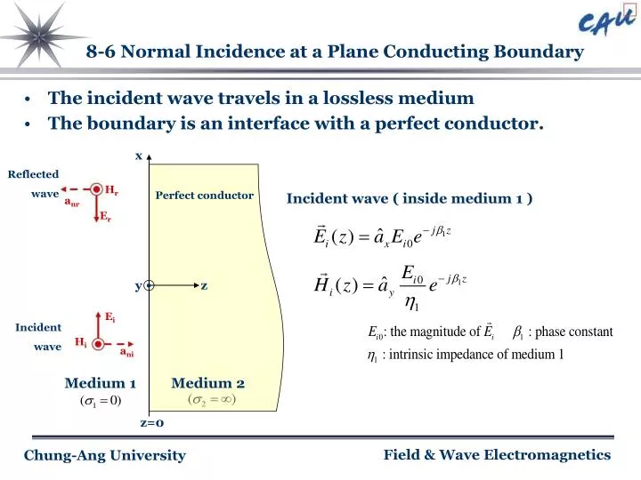
x Hr Perfect conductor anr Er . y z Ei Medium 1 Hi ani Medium 2 z=0 8-6 Normal Incidence at a Plane Conducting Boundary The incident wave travels in a lossless medium The boundary is an interface with a perfect conductor. Reflected wave Incident wave ( inside medium 1 ) Incident wave
Inside medium 2 , both electric and magnetic fields vanish No wave is transmitted across the boundary into the z > 0 . 8-6 Normal Incidence at a Plane Conducting Boundary Reflected wave ( inside medium 1 )
8-6 Normal Incidence at a Plane Conducting Boundary Total wave in medium 1 - continuity of tangential component of the E-field at the boundary z = 0
8-6 Normal Incidence at a Plane Conducting Boundary The space-time behavior of the total field in medium 1
x Standing wave. z ⅰ) vanishes on the conducting boundary. E1 versus z ⅱ) a maximum on the conducting boundary. ⅲ) The standing waves of and are in time quadrature ( 90˚ phase difference ). z H1 versus z 8-6 Normal Incidence at a Plane Conducting Boundary The total wave in medium 1 is not a traveling wave. Note following three points
x anr Perfect conductor Hr Er . y z ani Medium 1 Ei Hi Medium 2 z=0 8-7 Oblique Incidence at a Plane Conducting Boundary 8-7.1 Perpendicular Polarization Direction of propagation of incidence wave Reflected wave Incident wave ( inside medium 1 ) Incident wave
, for all x Snell’s law of reflection » the angle of reflction equals the angle of incidence. 8-7 Oblique Incidence at a Plane Conducting Boundary Direction of propagation of reflected wave Reflected wave ( inside medium 1 ) Boundary condition, z = 0
8-7 Oblique Incidence at a Plane Conducting Boundary Magnetic field of the Reflected wave
8-7 Oblique Incidence at a Plane Conducting Boundary Total field in medium 1
8-7 Oblique Incidence at a Plane Conducting Boundary In z-direction ( x=constant ) In x-direction ( z=constant ) C = f(z) , D = g(z)
when 8-7 Oblique Incidence at a Plane Conducting Boundary In x-direction or when
But, ( not transverse ) 8-7 Oblique Incidence at a Plane Conducting Boundary In x-direction , wave propagate ∴ TE wave • At A, A’’, O (intersection of the long and short dashed lines) → E=0 • At B ( intersections of two long dashed line) → E ( out of page ) is maximum . • At B’ ( intersections of two short dashed line) → E ( into the page ) is maximum . • Thes points travel in the +x direction Guided wavelength
x anr Er Perfect conductor Hr . y z Ei ani Medium 1 Hi Medium 2 z=0 8-7 Oblique Incidence at a Plane Conducting Boundary 8-7.2 Parallel Polarization Direction of propagation of incidence wave Reflected wave Incident wave ( inside medium 1 ) Incident wave
( for all x) 8-7 Oblique Incidence at a Plane Conducting Boundary Direction of propagation of reflected wave Reflected wave ( inside medium 1 ) Boundary Condition
In z-direction : standing-wave In x-direction : traveling wave. ( phase velocity : ) ∴ TM wave where 8-7 Oblique Incidence at a Plane Conducting Boundary Total field in medium 1 nonuniform plane wave
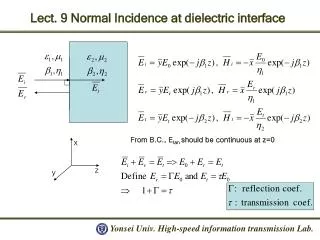
x Et Er anr ant Ht Hr . y z Ei Hi ani Medium 1 Medium 2 z=0 8-8 Normal Incidence at a Plane Dielectric Boundary Incident wave ( inside medium 1 ) Reflected wave Transmitted wave Reflected wave ( inside medium 1 ) Incident wave Transmitted wave ( inside medium 2 )
The tangential components (the x-components) of the electric and magnetic field intensities must be continuous. ( at interface z=0 ) Reflection coefficient ( + or - ) ≤ 1 E/H, E=0 perfect conductor !! H(I)=0 No current !! 8-8 Normal Incidence at a Plane Dielectric Boundary
If medium 2 Perfect conductor 8-8 Normal Incidence at a Plane Dielectric Boundary Transmission coefficient ( + always ) Totally reflected . Standing wave produced in medium 1 .
If medium 2 is not a perfect conductor , partial reflection will result . traveling standing 8-8 Normal Incidence at a Plane Dielectric Boundary
For dissipationless media are real . However, can be positive or negative. ⅰ) - Maximum value of is , which occures when - Minimum value of is , which occures when 8-8 Normal Incidence at a Plane Dielectric Boundary
ⅱ) - Maximum value of is , at - Minimum value of is , at Standing wave Ratio(SWR) 8-8 Normal Incidence at a Plane Dielectric Boundary if = 0, S=1: No reflection, full power transmission if = 1, S= : Total reflection, no power transmission
8-8 Normal Incidence at a Plane Dielectric Boundary Transmitted wave