Download
1 / 18
240 likes | 507 Views
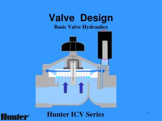
Valve Body Service. Transmission Overhaul. The transmission has been disassembled, and here is the valve body with transfer plate and gaskets. Worm Tracks. The worm tracks (fluid passages) provide a lot of places to collect and hold dirt and debris. Complex. Worm Tracks.

E N D
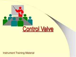
Valve Body Service Tom Birch, 6/07
Transmission Overhaul The transmission has been disassembled, and here is the valve body with transfer plate and gaskets. Tom Birch, 6/07
Worm Tracks The worm tracks (fluid passages) provide a lot of places to collect and hold dirt and debris. Tom Birch, 6/07
Complex Worm Tracks These views of a disassembled valve body from an electronic transmission show how complex they can be. Tom Birch, 6/07
VB Service Valve bodies are normally disassembled for cleaning during transmission repair, to cure a particular problem, or to stop a leak. Tom Birch, 6/07
Leaks Valve The bore plug can include an O-ring when that end of the valve has to hold fluid pressure. An old, hardened O-ring is normally replaced. Some bore plugs use a tight fit to hold fluid. Spring O-ring Bore Plug Another cause for fluid leakage is a blown gasket or loose mounting bolts. Tom Birch, 6/07
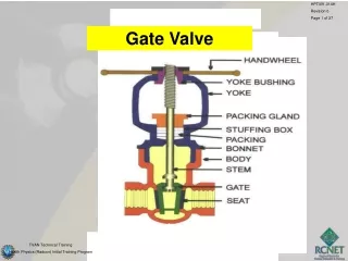
Components This cutaway view shows 15 valves (light blue), 5 solenoids (yellow), springs (red), bore plugs, (dark blue), retainers (green), a sleeve (orange), and an accumulator (brown). Tom Birch, 6/07
C 2 The retainers hold the bore plug or solenoid in place. Bolts, spring clips, or pins are commonly used. Tom Birch, 6/07
Service Information Service information can help guide the technician as to the proper procedure, the name of the components and where they are located. It also provide torque specifications for the various bolts. Tom Birch, 6/07
SI 2 Service information also provides the locations of the check balls. Tom Birch, 6/07
Disassembly A valve group can be slid out of the bore after the retainer has been removed. Note that it becomes very easy to mix up the parts if all are removed at the same time. Tom Birch, 6/07
Valve Holder A piece of heavy paper can be accordion folded to become a simple, inexpensive valve group holder. Tom Birch, 6/07
Organizing As each valve group is removed from it’s bore, it is placed in the holder. Some technicians will write the name of the valve on the holder to help learn the valve body. Tom Birch, 6/07
O 2 You can also add notes for future reminder. The valves can be kept clean and in correct order. Tom Birch, 6/07
Stuck Valves Technicians check valve movement by prying the valve toward the spring using a small screwdriver or seal pick; be very careful to not make a burr on the valve edge. Some blow air into the cavity at the opposite end from the spring. The valve should slide along the bore and then spring back when released. Tom Birch, 6/07
Spring SD Some sources provide spring specifications to help identify a particular spring; this can include wire diameter: WD, spring diameter: SD, and free length: FL. WD FL Tom Birch, 6/07
Gaskets Upper Body Two-part valve bodies often use a transfer plate with two gaskets, and these gaskets are usually different. Be carefully to install a gasket that is the same as the one that was removed. Upper Gasket Transfer Plate Lower Gasket Tom Birch, 6/07 Lower Body
Tighten the Retaining Screws Valve body halves should be held together tight and even to prevent leaks and gasket blow-out. Most technicians begin in the center and work outward in a spiral pattern. This is done, three or four times, working up from snug the first time to thespecified torque the last time. Tom Birch, 6/07