Download
1 / 36
390 likes | 648 Views
Gas Furnaces II. North Seattle Community College HVAC Program Instructor – Mark T. Weber, M.Ed. Gas Furnaces 2. Gas Furnaces. Configurations Up flow. Down or counter flow. Horizontal.

E N D
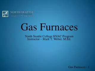
Gas Furnaces II North Seattle Community College HVAC Program Instructor – Mark T. Weber, M.Ed. Gas Furnaces 2
Gas Furnaces Configurations • Up flow. • Down or counter flow. • Horizontal. • In up flow furnaces the return air enters the bottom of the furnace, and moves across the heat exchanger and exits at the top of the furnace. • With down flow or counter flow furnaces the return air enters the top of the furnace, passes across the heat exchanger and is discharged at the bottom of the furnace. • With horizontal furnaces the return air enters at one end, passes across the heat exchanger and exits at the opposite end
Gas Furnaces Installation locations • Up flow / Basement. • Supply: • Floor; and • Low outside wall. • Return: • Low inside wall; • High inside wall; and • Ceiling.
Gas Furnaces Installation locations • Up flow / Attic installation. • Supply: • Ceiling; floor and • High inside wall. • Return: • Low inside wall; floor • High inside wall; and • Ceiling. The up flow furnace may be installed in an attic with a ceiling or high inside wall distribution supply-duct system and either a low sidewall or ceiling return-duct systems. If the high inside wall supply system is used, the supply duct system can be installed in fur downs in the top of closets and hall ways. This type of application is most commonly used to condition the upper floors of the structure. When installing a furnace in an attic, most codes require a floored area extending at least 3 feet on the service side of the system to accommodate service, and a floored walkway from the attic access to the equipment. Be sure to check local codes. If a cooling coil is installed with furnace, an auxiliary drain pan also is required. The auxiliary drain from the drain pan should be terminated at a conspicuous point to alert the consumer that a problem exists with the primary drain. Some codes allow the use of a condensate sensor in the auxiliary drain pan instead of the auxiliary drain line. If the code allows and the sensor is used, it must be wired to shut down the system if condensate is sensed in the drain pan.
Gas Furnaces Installation locations • Up flow / Floor level. • Supply: • Ceiling; and • High inside wall. • Return: • Ceiling; • High inside wall; and • Low inside wall. The up flow furnace may be installed at floor level in a closet with a ceiling-distribution supply-duct system and either a low or high inside wall or ceiling return-duct systems.
Gas Furnaces Installation locations • Down flow / Crawl space or slab floors • Supply: • Floor level. • Return: • Low inside; • High inside; and • Ceiling. With down flow furnaces the return air enters at the top of the furnace, passes across the heat exchanger and exits to the supply duct system at the bottom of the furnace. Down flow furnaces are normally set at floor level. Down flow furnaces are normally installed with either crawl-space or concrete-slab construction.
Gas Furnaces Installation locations • Horizontal / Attic • Supply: • Ceiling. • Return: • Ceiling; • High inside wall; and • Low inside wall. • Auxiliary drain pan must be installed. • Check local codes for access and flooring requirements. Horizontal furnaces can be installed in attics with ceiling supply and ceiling, high sidewall or low sidewall return-duct systems. When installing a furnace in an attic, most codes require a floored area extending at least 3 feet on the service side of the system to accommodate service, and a floored walkway from the attic access to the equipment. Be sure to check local codes. If a cooling coil is installed with furnace, an auxiliary drain pan is also required. The auxiliary drain from the drain pan should be terminated at a conspicuous point to alert the consumer that a problem exist with the primary drain. Some codes allow the use of a condensate sensor in the auxiliary drain pan instead of the auxiliary drain line. If the code allows, and the sensor is used it must be wired to shut down the system if condensate is sensed in the drain pan.
Gas Furnaces Installation locations • Horizontal / Basement • Supply: • Floor; and • Low outside wall. • Return: • Low inside wall; • High inside wall; and • Ceiling. • Check Local Codes for: • Auxiliary drain pan requirements.
Gas Furnaces Components Blower control boards; Condensate drains; Fan-limit switches; Flame-rollout switches; Burners; Blowers; and Motors. • Transformers; • Thermostats; • Heat anticipators; • Draft inducers; • Air-pressure switches; • Gas valves; • Heat exchangers;
Transformer • Steps down line voltage to 24-V control voltage. • Line side (primary). • Load side (secondary). • Rated in “VA”: • Volt-Ampere. • 40 VA means that the control voltage times amp draw cannot exceed 40. The function of the transformer is to “step down” the supplied line voltage to the 24-V control voltage used to provide power to the ignition control, gas valve and thermostat (and other controls, depending on the furnace model). The VA (volt-ampere) rating of the transformer represents the secondary output voltage (V) times the maximum current draw (A) that it can supply without overheating. For example, a 40-VA transformer (common for residential applications) can provide 1.667 A at 24 V on the secondary side. This can be calculated easily by dividing the VA rating by the control voltage (40 VA ÷ 24 V = 1.667 A). The maximum current draw of all components on the 24-V side should not exceed 1.667 A. If the current draw does exceed the transformer’s VA rating—which may happen because of a short or because too many components are connected to the secondary side of the transformer—either the secondary or the primary windings of the transformer may fail “open.” A symptom of an open winding is that line voltage can be measured on the line side of the transformer, but no voltage is measurable on the load side of the transformer.
Transformer: Measuring Resistance • Ohmmeter can verify if the secondary is open. • “Open” reading indicates secondary is open. • Replace. • Some may have circuit breakers or fuses.
Thermostat and Connections • Follow manufacturer’s mounting instructions. • Typical terminal designations are shown here. • Connected to corresponding terminals at the furnace.
Gas Furnaces Components • Thermostats – Electronic • Powered: • 24 V common must be connected. • Heat anticipation is built into electronic memory. • Power stealing: • 24 V common not used. • Not compatible with all systems. • Check manufacturer’s recommendations. • Heat anticipation is built into electronic memory.
Heat Anticipator • Prevents wide swings in temperature. • Cycles furnace off slightly before setpoint is reached. • Ammeter method is shown. • Thermostats may have a cycle rate adjustment instead. Heat anticipators are built into many mechanical thermostats to prevent wide swings in room temperature during furnace operation. They allow a furnace to cycle off slightly before the desired setpoint is attained, allowing the residual heat in the furnace and duct system to bring the room temperature up to the setpoint without exceeding it. Heat anticipators are energized during the “ON” cycle. To set resistance-type anticipators, measure the actual current draw in the control circuit (terminal R to terminal W) using a low-range ammeter. Wait until the main furnace blower cycles on and note the reading on the meter. Once the current draw has been determined, set the heat anticipator to match that value. If a low-range ammeter is not available, use a clamp-on type. Wrap exactly ten turns of wire around the jaws of the ammeter. Connect one end of the wire to the W terminal of the thermostat subbase, and the other to the R terminal. Turn the power on. The furnace will begin the heating cycle. Wait until the main furnace blower cycles on and note the reading on the meter. Divide the meter reading by 10 to obtain the correct anticipator setting.
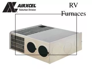
Inducer • Brings in combustion air. • Expels flue products. • First step in sequence of operation. • Not field-repairable. • Operation is proven by pressure switch.
Inducer The inducer, also referred to as an “induced-draft blower” or a “combustion blower,” serves two functions. It brings air for combustion into the burner box, and expels the products of combustion from the heat exchanger to the outdoors. On a call for heat in most gas furnaces, the first step in the sequence of operation is to energize the inducer. This is typically done through the ignition control board when a call for heat is received from the thermostat. The inducer motor is energized with line voltage, and the inducer wheel begins turning to create air movement. Air travels from the combustion air supply, through the burner area, through the heat exchanger(s), and to the outdoors through the flue (exhaust) pipe. Inducer assemblies normally are not field-repairable. If any portion of the inducer assembly fails, such as the motor or wheel, the entire assembly usually is replaced. Check with the equipment manufacturer for proper procedures regarding inducer repair or replacement. The inducer’s performance is critical to the safe and efficient operation of the furnace. The proper operation of the inducer is verified by the next component, the pressure switch.
Pressure Switch • Verifies that inducer is operating and that there are no restrictions. • Most are “normally open.” • Close after inducer is energized.
Pressure Switch • “Make” point is usually on the switch body. • Closure may be verified by taking a voltage reading. • 24 volts if the switch is open; and • 0 volts if the switch is closed. • May also be verified with an ohmmeter; • Disconnect wiring first.
Pressure Switch • If the switch doesn’t close, the cause must be determined. • Use diaphragm-type pressure gauge or an inclined manometer; • Place in parallel with switch.
Pressure Switch • If measured pressure exceeds switch closure rating and switch is not closing, switch is defective. • If measured pressure is less than closure rating, check for restrictions: • Snow, ice, insect nests, and undersized piping.
Gas Valve • Meters flow of gas. • Most OEM equipment is configured for natural-gas application: • Converted for LP gas; and • Burner orifices are changed for LP-gas applications. • Has an inlet, outlet, connection terminals and means of pressure adjustment. • Not field serviceable.
Electronic Blower Control • Timed on and off blower operation: • Often field-selectable. • Many more functions.
Condensate Drain • Found in high-efficiency furnaces. • Water vapor condenses from flue products. • Condensate runs from secondary heat exchanger into drain trap. • Fill trapwith water upon installation. In a high-efficiency furnace, enough heat is extracted from the products of combustion that the water vapor condenses out into the secondary heat exchanger. After exiting the heat exchanger, the condensate enters the condensate drain trap. The drain trap allows the condensate to drain properly. The condensate drain trap should be primed (filled with water) upon installation. If it is not, there may be issues with the pressure-switch operation.
Limit Switches • Prevents operation during abnormal temperatures. • If the main limit switch is opening, check these areas: • Gas pressure; • Blower speed; • Static pressure; • Proper furnace size; • Clean blower wheel; and • Inspect for debris. • Exact replacement only.
Limits: Auxiliary and Rollout • Auxiliary limits are often found on counterflow models: • Blower compartment. • Rollout switches: • Burner area; and • Manual reset. Rollout limit switches are located in the burner area. Depending on the furnace model, there may be one or more rollout switches present. The rollout limit switch opens in the event of an abnormal flame pattern. In systems that have inshot burners, the flames should be fired directly through the vestibule panel and into the heat exchanger. If burners are misaligned, gas pressure is incorrect, orifices are improperly sized or misaligned, or a restriction or leak is present in the heat exchanger, rollout can occur. The rollout limit switch shown here is a snap-action thermostat with manual reset. A rollout limit switch trip needs to be thoroughly investigated and corrected. Never bypass any limit switch in order to allow operation to continue. Doing so can result in hazardous conditions leading to property damage, bodily injury or loss of life.
Burners: Inshot • Used with serpentine or tubular heat exchangers. • Gas and air mix in the throat. • No air adjustments. • Flame spreads with carryover channel.
Burners: Ribbon • Used with “clamshell” heat exchangers. • Flame extends out the top. • Flame carryover may be built in or separate. • Outlet ports are susceptible to restriction by debris. • Almost never used today.
Heat Exchanger • Transfers heat from burned fuel to air. • Single heat exchanger: • Non-condensing furnaces. • Second heat exchanger: • Condensing furnaces.
Blower Assembly • Circulates air. • PSC (permanent split-capacitor) is most common. • Multispeed: • Adjusted by technician; • Color-coded leads; and • One speed energized at a time.
Variable Speed Blowers • Can overcome some resistance in duct system. • Does have limitations. • Gradual “ramp” to speed. • Supplied with ac voltage, converted to dc. As the resistance to air flow increases in the duct system, the performance of a PSC blower declines. Many of the higher-efficiency model furnaces are available with variable-speed blowers, which have gained great popularity. A variable-speed blower is able to overcome a degree of resistance in the duct system and still maintain the proper cfm through the system. For instance, as the filter becomes dirty, the variable-speed blower can ramp up to a higher speed to overcome the additional resistance. Variable-speed blowers do have limitations, however. If higher-than-normal resistance is present in the duct system (e.g., 1.0 in. w.g. total ESP), an excessive amount of noise will be noticeable as the blower ramps up to attempt to overcome this resistance. Another popular feature of the variable-speed blower is that it gradually ramps up to speed when starting, and gradually ramps down when the cycle is completed. In many cases, the starting and stopping of the blower motor will not be noticeable from the living space.
Line Pressure Measurement • Measured at inlet of gas valve. • Must not exceed recommendations. • 7-in. w.g. is typical for natural gas. • 12-in. w.g. is typical for LP gas.
Manifold Gas Pressure • Measured at outlet of gas valve. • Verify that manometer and burners are under the same pressure. • Adjustment are made under cap on gas valve. • Set to manufacturer value. • Inspect flames.
Temperature Rise Measurement • Difference between return and supply temperatures. • Must fall within range on the rating plate. • Increase blower speed to decrease temperature rise. • Decrease blower speed to increase temperature rise.
Sequence of Operation • An understanding of the sequence is critical to success as a service tech. • Typical Sequence: • A call for heat occurs when the thermostat closes the R-W circuit; • The induced-draft blower starts; • The operation of the induced-draft blower is proven; • The ignition sequence begins; • Flame is established and proven; and • The main blower is energized.