Download
1 / 19
190 likes | 359 Views
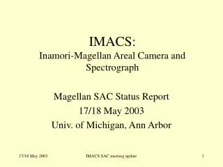
MMT Magellan Infrared Spectrograph ( MMIRS ). P.I. Brian McLeod Warren R. Brown SAO/CfA. Science Drivers – Star formation at high redshift. (Erb 2006). Science Drivers – Brown dwarfs. Multi-Slit Spectrograph. (Image from Flamingos). Detector. Slit Mask. Basic Operational Modes.

E N D
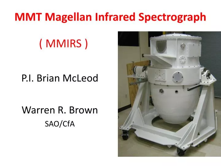
MMT Magellan Infrared Spectrograph( MMIRS ) P.I. Brian McLeod Warren R. Brown SAO/CfA
Science Drivers – Star formation at high redshift (Erb 2006)
Multi-Slit Spectrograph (Image from Flamingos) Detector Slit Mask
Basic Operational Modes • Imaging • 6.9 x 6.9 arcminute FOV • 0.202 arcsecond pixels • Y, J, H, Ks wavelength coverage • Spectroscopy • Multi-slit (4′x7′) or longslit (7′) • J, H, K @ R=3500 • H+K @ R=1300
TELESCOPE TRUSS ASSEMBLY WITH BOLT INTERFACES TO TELESCOPE & CRYOSTAT SLITMASK SECTION (2) GUIDER/ WFS ELECTRONICS RACKS MOS SECTION TRUSS ELECTRONICS RACK TRUSS (2) DETECTOR PRE-AMP’S OPTICS + DETECTOR SECTION MMIRS EXTERIOR
Filter and Grism Wheels Collimator Detector Camera Slit Masks Corrector Optics (warm) LN2 Tank/ Optical Bench Dekker Guider/WFS (warm) MMIRS INTERIOR
MMIRS Field of View Imaging field Guide camera patrol area 7x7 arcmin D = 14 arcmin A = 50 arcmin2 ea Slit masks Guider FOV 80” 4x7 arcmin, central 2′x7′ with full wavelength coverage
Detector Information HAWAII-2 2k x 2k HgCdTe detector • Full well 230,000 e- • Readnoise 16 e-(per pair of reads) • Dark current 0.05 e-/s/pix at 83 K (temp dependent) • Readout: 32 channels at 180 kHz = 0.7 sec • CMOS device Bad pixelsDark currentFlat field
Observed Image Quality 1.1 pixel FWHM
Imaging Information • Filters: Y, J, H, Ks • Sky background: narrow OH emission and broad H2O absorption. • Images unguided • ~5 sec overhead between exposures, including telescope dither.
Imaging Sensitivity Magnitude of point source (Vega mag) with S/N=10 Exposure Time Calculator: http://www.cfa.harvard.edu/mmti/mmirs.html
Spectroscopic Information • Dispersed Spectra: 1400 pixels long • Field for complete spectra: 2 x 6.9 arcmin • Full field for spectroscopy: 4 x 6.9 arcmin • 9 slit masks, 7 long slits: 420 x 0.2, 0.4, 0.6, 0.8, 1.0, 1.2, 2.4” • Up to 40 slitlets, of minimum length 10”
Spectroscopic Sensitivity Lab test: real spectra. Expected S/N per resolution element at R=3000 Slit mask Spectra
Schedule • March/April 2009 • ~1 week engineering run • May/June 2009 • ~2 week science “commissioning” • Magellan 2010 (MMIRS and Megacam)
THE WEB SITE http://www.cfa.harvard.edu/mmti/mmirs.html THE TEAM Principal Investigator: B. McLeod Instrument Scientists: G. Furesz, P. Martini Optical design consultant: H. Epps Co-Investigators: D. Fabricant, J. Geary, S. Kenyon, W. Brown P. McCarthy, E. Persson, S. Eikenberry Project Manager: T. Norton Project Engineer: G. Nystrom Engineering Staff: K. McCracken, J. Holwell, M. Burke, S. Amato, J. Zajac, H. Bergner, S. Park, E. Hertz Software: D. Curley, M. Conroy, J. Roll, W. Wyatt Technicians: W. Brymer, F. Collette Machinists: K. Bennett, L. Knowles, and the Harvard Model Shop Commissioning Team: A. Seth, W. Brown, D. Fabricant, B. McLeod