Download
1 / 73
730 likes | 735 Views
Studying the “brain” realization and its simulated quantum implementation for the Cynthia robot. Contents. Introduction to Cynthia robot. The goal of the research. Examples of different explanations of the brain system The research plan. Overview on the previous work. Simulation steps

E N D
Studying the “brain” realization and its simulated quantum implementation for the Cynthia robot
Contents • Introduction to Cynthia robot. • The goal of the research. • Examples of different explanations of the brain system • The research plan. • Overview on the previous work. • Simulation steps • Current work (Project) • Future work.
The goal of the research • To build a block which will act as a brain on top of the MNS and NNS. • This block will control the behavior of the robot such that it reflects the learning process of the robot as well as the physical phenomena that might happened and affect the robot behavior similar to the real brain. - That requires us to study the biological brain systems
W11 W12 W21 AF output SUM (Wij) W31 W13 W41 W14 W51 Examples of different explanations of the brain system • Gerald Edelman Neural Darwinism: • The Theory of Neural Group Selection.
1 1 0 1 0 1 Neural Darwinism: The Theory of Neural Group Selection.
Examples of different explanations of the brain system • StappThe Brain as a Quantum Measuring Device The neural wave function enfolds superposed possibilities, and then consciousness chooses one classical branch and annihilates the others. The choice is "unruly," Stapp (1993, p.32) says. • Some Physical Phenomena couldn't be represented by any low or mathimatical equations • Twins spiritual link • It is believed that this could be explained using one of the quantum mechanics features, called , Entanglement
Examples of different explanations of the brain system • YasueQuantum Brain Dynamics and Consciousness: An Introduction (Advances in Consciousness Research, V. 3 • Water Mega molecule • Ben GoertzelEvolutionary Quantum Computation: • Its Role in the Brain, Its Realization in Electronic Hardware, and Its Implications for the Pan psychic, Theoryof Consciousness • Populations of neuronal maps have a quantum aspect as well as a classical. The brain is an evolving population of quantum neural networks
Examples of different explanations of the brain system • Set up an ensemble of quantum computers, and allow them to evolve. • Create criteria for judging QC's, and then, in the manner of natural selection, allow successful QC's to survive and (probabilistically) mutate and combine to form new candidate QC's, whereas unsuccessful QC's perish. • The result is that one has quantum computers fulfilling desired functions via unknown means.
Quantum System &Theory E24= (0 1 0 0) • Hilbert Space E14= (1 0 0 0) X E34= (0 0 1 0) E1 E2 E3 E4 are orthonormal vectors and called the bases of the Hilbert space
E24= (0 1 0 0) r E14= (1 0 0 0) X E34= (0 0 1 0) Quantum System &Theory • Hilbert Space
Quantum System &Theory • Quantum system • Quantum systems are described by a wave function, r , that exists in a Hilbert space. • The Hilbert space has a set of states, Ei , which is called the set of bases, and the system is described by a quantum state, r , which is said to be in a linear superposition of the basis states Ei , and in general, the coefficients are complex numbers.
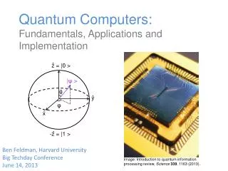
Qubit • State • Super position • Uncertainty Quantum Theory
Quantum Theory 0 0 Block Sphere 1 Classical BIT 1 QuBIT
Quantum Theory • Measures the qubit state The quantum system is said to be collapsed when we make the projection on one of the basis. That is also called decoherence or the measures. For example, if we take the projection of on the |0> basis then it will be . is the probability of the qubit to collapse on the state |0>.
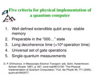
Why quantum • The increasing speed of the computations as well as reducing the size of the computers will lead to the quantum mechanics theory will replace the classical logic theory. • Implementation of models of the physical phenomena that could not be implemented before. • Reduction in time and increase in memory capacity. • Parallelism
Quam using Grover algorithm Storing Pattern algorithm Pattern recall algorithm For a set of m binary patterns with length n, 2n+1 qubits are required Research algorithm the speed of researching is O( ). SPEED OF WHAT???
Storing Pattern algorithm A quantum algorithm for constructing a coherent superposition of states (bases), that corresponds to the patterns, with the amplitudes of the states in the superposition all being equal. |f> = |X1 X2……Xn > Where X1,X2,….,Xn are n qubits to represent the n bits for every binary pattern of the m patterns. For example |f > = |10110100> + |11000011> +……..
Storing Pattern algorithm • To construct this wave function we need to use n+1 qubits to be used in the process of generation the function. • |f> = |X1 X2……Xn, G1G2…..Gn-1, C1C2> • G1, G2, Gn-1 as well as C1 C2 are control registers.
Storing Pattern algorithm • Three transformation are used in the process of generating the function • S state generation explain Where s is the values of the F(z) and s {1,-1} and 1 <= P <=m.
Storing Pattern algorithm • Control flip transformation Let’s consider two qubits
Storing Pattern algorithm • Control flip transformation Let’s consider two qubits
Storing Pattern algorithm • AND transformation Let’s consider three qubits
Storing Pattern Algorithm Explain all symbols
Storing Pattern Algorithm Step by Step example To understand the algorithm, let’s assume the following set of learning patterns D = {f(01) = -1, f(10) = 1, f(11) = -1} From D we can deduce the following Z3 is 01 Z2 is 10 Z1 is 11 n = 2 number of qubit to represent the patterns m=3 number of patterns to be represented
Storing Pattern Algorithm Step by Step example 1- |f > = |00,0,00 > X1=0 X2=0 g1=0 , C1=0 and C2 =0 2 2- do the for loop P=3 Z3= 01 Z31=0 Z32=1 Z4= 00 Z41=0 Z42=0 Z32 notequal Z42 flip X2 X2 C2 X2 Then |f > = |01,0,00 >
Storing Pattern Algorithm Step by Step example 3- Flip C1 state C1 C2 C1 Then |f > = |01,0,10 >
Storing Pattern Algorithm C1 4- Generate a new state by applying S on C2 C1 C2 then |f > = -1/ |01,0,11 > + |01,0,10>
Storing Pattern Algorithm • 5- Flip g1 to mark the register g1 X1 X2 g1 then |f > = -1/ |01,1,11 > + |01,1,10>
Storing Pattern Algorithm 26- Flip C1 which is controlled by g1 g1 C1 C1 then |f > = -1/ |01,1,01 > + |01,1,00>
Storing Pattern Algorithm • 5- Flip g1 again to the normal state g1 X1 X2 g1 then |f > = -1/ |01,0,01 > + |01,0,00> Saved Go to step 1Again
Storing Pattern Algorithm • The whole process repeated again with start |f > = -1/ |01,0,01 > + |01,0,00> after the 3rd loop |f> = that is what is called storing the pattern.
5 qubit Quam Network Implemantation X1 ?F0 A0 X2 ?F0 A0 g1 F1 C1 F0 S C2
Pattern recall Algorithm • The idea of pattern recall is collapsing the function |f > on the required basis (pattern). • Grover used his quantum search in data base algorithm in • recalling the pattern. The idea of this search is to change the phase of the desired state and then rotate the entire |f > around the average. This process repeated (3.14/4)* Where N is the total possible state.
Pattern recall Algorithm • The algorithm steps: 1-change the phase of the desired state. 2- compute the average A 3- rotate the entire quantum set around the average. |f>= 2A-|f > 4- repeat 1-3 for (3.14/4)* 5- Measure the desired state.
Pattern recall Algorithm • Step By Step example Let’s continue on the same example, used in the learning phase. Let’s assume we want to recall the pattern 01. Since we have only 2 qubits then the possible combination is 4. |f> will collapse on the desired state after repeat the algorithm for (3.14/4)*2, which roughly 1 times.
Pattern recall Algorithm 1- |f > 2 2- f > 1/ (0,-1,1,1) 3- 3- Average =1/4 4- 4- |f > 1/2 (1,3,-1,-1) 5- 5- Measure the desire state |f >= ( /2) |01> • Step By Step example
Pattern recall Algorithm • It is obvious that the probability of the system to collapse on the desired state is ¾= 75%. • Thesystem collapse in the O( ). • Which means it is faster than the classical NN which takes O(N)
Comparison between the Quam and the NN Hope field Associative memory.
Comparison between the Quam and the NN Hope field Associative memory.
The research plan Phase One • Insert a quantum circuit in the command execution data path, in the MNS in figure.1. The quantum circuit will alter the command slightly. • Phase Two • Phase Three
Phase One Robot (CRL parcel translator) MNS ( command initiation) Quantum Circuit ( Command alteration) Servos (Motion)
Phase Two • Study designing the quantum circuit such that it reflects the learning process of the robot brain and matches the behavior, mode and the emotion of the robot.
Robot (CRL parcel translator) MNS ( command initiation) Quantum Circuit ( Command alteration) Servos (Motion) Phase Two Quantum Circuit ( Design the matched Quantum circuit to the required behavior )
Phase Three Robot Brain • Generalize the Idea by built in a complete block on top of the MNS , which will act as a brain to the robot.
Overview on the previous work A quantum circuit was introduced using the QUASI quantum simulator. The theatre robots communicate using CRL (Common Robotic Language). The inputs for the Quantum circuit will be the data between the command tags in the CRL file. The present version supports only the following command tags for the recognition of inputs to the Quantum Circuit. They are wait, flush, move, normal, smile, frown, cry, look, speak, speed, accel, open and close.
Simulation steps: Robot (CRL parcel Command translator) Choose Quantum circuit using Quasi Simulator Save the circuit into XML data File Save input data into XML File Load the XML files Using Quasi Simulator Generate the Output sequence from the circuit and save in a file to be used as an alter command to the servo
Current work (project) • Integrate the software which was done in the previous work. (current) Robot (CRL parcel Command translator) Choose Quantum circuit using Quasi Simulator Generate the Output sequence from the circuit and as an alter command to the servo