Download
1 / 261
5.46k likes | 7.48k Views
Fundamentals of Instrumentation & Process Control Interactive Training Workshop. Fundamentals of Instrumentation & Control. Introduction to Process Control.

E N D
Fundamentals of Instrumentation& Process ControlInteractive Training Workshop
Introduction to Process Control A common misconception in process control is that it is all about the controller – that you can force a particular process response just by getting the right tuning parameters. In reality, the controller is just a partner. A process will respond to a controller’s commands only in the manner which it can. To understand process control you must understand the other partners as well: sensors, final control elements and the process itself. All of these determine what type of response the controller is capable of extracting out of the process. It is not the other way around.
Introduction to Process Control • Objectives: • Why do we need process control? • What is a process? • What is process control? • What is open loop control? • What is closed loop control? • What are the modes of closed loop control? • What are the basic elements of process control?
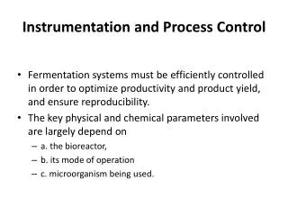
Motivation for Automatic Process Control • Safety First: • people, environment, equipment • The Profit Motive: • meeting final product specs • minimizing waste production • minimizing environmental impact • minimizing energy use • maximizing overall production rate
“Loose” Control Costs Money It takes more processing to remove impurities, so greatest profit is to operate as close to the maximum impurities constraint as possible without going over It takes more material to make a product thicker, so greatest profit is to operate as close to the minimum thickness constraint as possible without going under
“Tight” Control is More Profitable • A well controlled process has less variability in the measured process variable (PV), so the process can be operated close to the maximum profit constraint.
Terminology for Home Heating Control • Control Objective • Measured Process Variable (PV) • Set Point (SP) • Controller Output (CO) • Manipulated Variable • Disturbances (D)
What is Process Control • Terminology: • The manipulated variable (MV) is a measure of resource being fed into the process, for instance how much thermal energy. • A final control element (FCE) is the device that changes the value of the manipulated variable. • The controller output (CO) is the signal from the controller to the final control element. • The process variable (PV) is a measure of the process output that changes in response to changes in the manipulated variable. • The set point (SP) is the value at which we wish to maintain the process variable at.
What is a Process • A process is broadly defined as an operation that uses resources to transform inputs into outputs. • It is the resource that provides the energy into the process for the transformation to occur.
What is a Process • Each process exhibits a particular dynamic (time varying) behavior that governs the transformation. • That is, how do changes in the resource or inputs over time affect the transformation. • This dynamic behavior is determined by the physical properties of the inputs, the resource, and the process itself.
What is a Process • Can you identify some of the elements that will determine the dynamic properties of this process?
What is Process Control • Process control is the act of controlling a final control element to change the manipulated variable to maintain the process variable at a desired set point. • A corollary to our definition of process control is a controllable process must behave in a predictable manner. • For a given change in the manipulated variable, the process variable must respond in a predictable and consistent manner.
What is Open Loop Control • In open loop control the controller output is not a function of the process variable. • In open loop control we are not concerned that a particular set point be maintained, the controller output is fixed at a value until it is changed by an operator. • Many processes are stable in an open loop control mode and will maintain the process variable at a value in the absence of a disturbances. • Disturbances are uncontrolled changes in the process inputs or resources.
What is Open Loop Control • Can you think of processes in which open loop control is sufficient?
What is Closed Loop Control • In closed loop control the controller output is determined by difference between the process variable and the set point. Closed loop control is also called feedback or regulatory control. • The output of a closed loop controller is a function of the error. • Error is the deviation of the process variable from the set point and is defined asE = SP - PV.
What is Closed Loop Control • From the controllers perspective the process encompasses the RTD, the steam control valve, and signal processing of the PV and CO values.
What are the Modes of Closed Loop Control • Closed loop control can be, depending on the algorithm that determines the controller output: • Manual • On-Off • PID • Advanced PID (ratio, cascade, feedforward) • or Model Based
What are the Modes of Closed Loop ControlManual Control • In manual control an operator directly manipulates the controller output to the final control element to maintain a set point.
What are the Modes of Closed Loop ControlOn-Off Control • On-Off control provides a controller output of either on or off in response to error.
What are the Modes of Closed Loop ControlOn-Off Control Deadband • Upon changing the direction of the controller output, deadband is the value that must be traversed before the controller output will change its direction again.
What are the Modes of Closed Loop ControlPID Control • PID control provides a controller output that modulates from 0 to 100% in response to error.
What are the Modes of Closed Loop ControlTime Proportion Control • Time proportion control is a variant of PID control that modulates the on-off time of a final control element that only has two command positions. • To achieve the effect of PID control the switching frequency of the device is modulated in response to error. This is achieved by introducing the concept of cycle time. Cycle Time is the time base of the signal the final control element will receive from the controller. The PID controller determines the final signal to the controller by multiplying the cycle time by the output of the PID algorithm.
What are the Modes of Closed Loop ControlCascade Control • Cascade control uses the output of a primary (master or outer) controller to manipulate the set point of a secondary (slave or inner) controller as if the slave controller were the final control element.
Basic Elements of Process Control • Controlling a process requires knowledge of four basic elements, the process itself, the sensor that measures the process value, the final control element that changes the manipulated variable, and the controller.
Understanding Dynamic Process Behavior • Dynamic Process Behavior – What It Is & Why We Care • What a FOPDT Dynamic Model Represents • Analyzing Step Test Plot Data to Determine FOPDT Dynamic Model Parameters • Process Gain, Time Constant & Dead Time • How To Compute Them From Plot Data • How to Use Them For Controller Design and Tuning • How to Recognize Nonlinear Processes What We Will Learn in This Section
Dynamic Process Behavior and Controller Tuning • Consider cruise control for a car vs a truck • how quickly can each accelerate or decelerate • what is the effect of disturbances (wind, hills, etc.) • Controller (gas flow) manipulations required to maintain set point velocity in spite of disturbances (wind, hills) are different for a car and truck because the dynamic behavior of each "process" is different • Dynamic behavior how the measured process variable (PV) responds over time to changes in the controller output (CO) and disturbances (D)
Graphical Modeling of Dynamic Process Data • To learn about the dynamic behavior of a process, we analyze measured process variable (PV) test data • PV test data can be generated by suddenly changing the controller output (CO) signal • The CO should be moved far and fast enough so that the dynamic behavior is clearly revealed as the PV responds • The dynamic behavior of a process is different as operating level changes (nonlinear behavior), so collect data at normal operating conditions (design level of operation)
Modeling Dynamic Process Behavior • The best way to understand process data is through modeling • Modeling means fitting a first order plus dead time (FOPDT) dynamic model to the process data: • where: • PV is the measured process variable • CO is the controller output signal • The FOPDT model is simple (low order and linear) so it only approximates the behavior of real processes
Modeling Dynamic Process Behavior • When a first order plus dead time (FOPDT) model is fit to dynamic process data • The important parameters that result are: • Steady State Process Gain, Kp • Overall Process Time Constant, • Apparent Dead Time, Өp
The FOPDT Model is All Important • FOPDT model parameters (Kp, and Өp) are used in correlations to compute controller tuning values • Sign of Kp indicates the action of the controller (+Kp reverse acting; —Kp direct acting) • Size of indicates the maximum desirable loop sample time (be sure sample time T 0.1 ) • Ratio of Өp/ indicates whether model predictive control such as a Smith predictor would show benefit (useful if Өp > ) • Model becomes part of the feed forward, Smith Predictor, decoupling and other model-based controllers
Step Test Data and Dynamic Process Modeling • Process starts at steady state in manual mode • Controller output (CO) signal is stepped to new value • Process variable (PV) signal must complete the response
Process Gain (Kp) from Step Test Data • Kp describes how far the measured PV travels in response to a change in the CO • A step test starts and ends at steady state, so Kp can be computed directly from the plot where PV and CO are the total change from initial to final steady state • A large process gain, Kp, means that each CO action will produce a large PV response
Process Gain (Kp) for Gravity-Drained Tanks • Compute PV and CO as “final minus initial” steady state values
Process Gain (Kp) for Gravity-Drained Tanks • Kp has a size (0.1); a sign (+0.1), and units (m/%)
Additional Notes on Process GainMeasuring the Process Gain • Process gain as seen by a controller is the product of the gains of the sensor, the final control element and the process itself. • The gain of a controller will be inversely proportional to the process gain that it sees
Additional Notes on Process GainConverting Units of Process Gain • There is one important caveat in this process; the gain we have calculated has units of m/%.Real world controllers, unlike most software simulations, have gain units specified as %/%. • When calculating the gain for a real controller the change in PV needs to be expressed in percent of span of the PV as this is how the controller calculates error.
Assuming the process gain of the gravity drained tanks is 0.1 m/% then, to convert to %/% Additional Notes on Process GainConverting Units of Process Gain
Additional Notes on Process GainValues for Process Gain • Process gain that the controller sees is influenced by two factors other than the process itself, the size of the final control element and the span of the sensor. • In the ideal world you would use the full span of both final control element and the sensor which would give a process gain of 1.0.
Additional Notes on Process GainValues for Process Gain • As a rule of thumb: • Process gains that are greater than 1 are a result of oversized final control elements. • Process gains less than 1 are a result of sensor spans that are too wide.
Additional Notes on Process GainValues for Process Gain • The result of a final control element being too large (high gain) is: • The controller gain will have to be made correspondingly smaller, smaller than the controller may accept. • High gains in the final control element amplify imperfections (deadband, stiction), control errors become proportionately larger. • If a sensor has too wide of a span: • You may experience problems with the quality of the measurement. • The controller gain will have to be made correspondingly larger making the controller more jumpy and amplifying signal noise. • An over spanned sensor can hide an oversized final element.