Download
1 / 39
390 likes | 548 Views
User Interaction Design. Representing User Interactions. Design & Representation. Design Creative, mental, problem-solving process Representation Physical process of capturing or recording a design. Design Representations. Means by which interaction designs are communicated and documented.

E N D
User Interaction Design Representing User Interactions
Design & Representation • Design • Creative, mental, problem-solving process • Representation • Physical process of capturing or recording a design
Design Representations • Means by which interaction designs are communicated and documented. • Design representations are communicated between: • Designer and developer (maybe others) • Not the User (in most cases)
Design Representations • Constructional Representations • Interactions described from the system’s view point. • State Transition diagrams • Event-based mechanisms • Object Oriented mechanisms
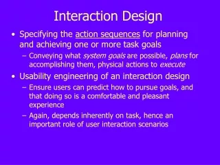
Design Representations • Behavioral Representations • User Centered and Task/Goal Oriented. • Task Analysis, user modeling, function analysis are all behavioral activities • Example Methods • Command Language Grammar • Keystroke Level Model • Task Action Grammar • GOMS (Goals, Operators, Methods & Selection) • User Action Notation (UAN)
User Interaction Design • Each Behavioral design must be translated into a Constructional Design • Result is the User Interaction Design • User Interaction Design is created by the designer and given to the developer.
User Action Notation • User and Task Oriented Notation that describes physical behavior of the user and interface as task are being performed.
User Action Notation • Interfaces are represented as quasi-hierarchical structures of asynchronous tasks. • User actions cause state changes in the interface.
User Action Notation • UAN consists of • Task Descriptions • Scenarios • Discussion Notes • State Transition Diagrams • Uses special Notation to describe tasks
UAN: Selecting A File • Move the cursor to the file icon. • Press and immediately release the left mouse button.
UAN: Selecting A File • ~[file icon] • Mv^
User Action Notation Advantage of UAN • Takes less space on paper. • If you know, it saves time.
User Action Notation Problems with UAN • New language for the developer. • Cryptic notation. • If you don’t know it, it takes more time. • No standard notation.
User Action Notation Modified • UAN consists of • Task Descriptions • Scenarios • Discussion Notes • State Transition Diagrams • Eliminate special Notation
Task Descriptions • Identify all of the tasks the system or product must support. • Occurs in Feasibility and Analysis Stage of Software Development.
Scenarios • Create User Scenarios that support each task from the Task Descriptions. • Occurs in Analysis and Design Stage of Software Development.
Discussion Notes • Any special observations, requirements or hypothesis that designer has are noted. • Occurs in everywhere in Software Development.
State Transition Diagrams • Finite State Machines • Graph of the system that identifies user interactions. • Occurs in Design before Development. • Includes graphs and screen images.
State Transition Diagrams • Graphs with Nodes and Edges. • Nodes • Represent interface states. • Image of interface should be included. • Edges • Appear between nodes. • Represent changes in interface state.
State Transition Diagrams • Each interface has a State Transition Diagram. • The system is a collection of interfaces, therefore, it is also a collection of State Transition Diagrams • Can become very complex very quick.
State Transition Diagrams • Each interface has a State Transition Diagram. • The system is a collection of interfaces, therefore, it is also a collection of State Transition Diagrams • Can become very complex very quick.
User Interaction Design Example Login Interface
Password Password Submit End Start Login Login Top path Bottom path
Password Submit End Start Login Top Path
Password Submit End Start Login Bottom Path
Password Password Submit End Start Login Login Top path Bottom path
Frontpad Rearpad Front,Rear,Both Rear,Both,Neither Front closed open Neither Automatic Door/FA Chuck Allison, UVSC, http://uvsc.freshsources.com/html/cns_3240.html
2 3 Free Ride Successful Path A successful path through a transition graph is a series of edges forming a path beginning at some start state (there may be several) and ending at a final state. abbab… abbaa… abb a abbababba 1- 4+ aa b A Lambda transition occurs when you get a free transition that was not initiated by user or system action/interaction. Move on a whim (w/o consuming input). Chuck Allison modified by Seals
Example(p. 84) b a,b a b - + bbb a a a ab b bbb bb bb a Cohen Ch6-Chuck Allison, http://uvsc.freshsources.com/html/cns_3240.html
User Interaction Design • Task Descriptions • Scenarios • Discussion Notes • State Transition Diagrams