Download
1 / 32
320 likes | 415 Views
CS 61C: Great Ideas in Computer Architecture (Machine Structures) Lecture 27: Single-Cycle CPU Datapath Design. Instructor: Sr Lecturer SOE Dan Garcia http:// inst.eecs.Berkeley.edu /~cs61c/. www.technologyreview.com/news/512891/software-makes-multiple-screens-less-distracting/.

E N D
CS 61C: Great Ideas in Computer Architecture (Machine Structures)Lecture 27: Single-Cycle CPUDatapathDesign Instructor: Sr Lecturer SOE Dan Garcia http://inst.eecs.Berkeley.edu/~cs61c/
www.technologyreview.com/news/512891/software-makes-multiple-screens-less-distracting/www.technologyreview.com/news/512891/software-makes-multiple-screens-less-distracting/ Technology In the News Software makes multiple screens less distracting Diff Displays from the University of St Andrews “uses eye-tracking software to sense when the user is not longer paying attention to a particular screen. It then replaces the content on that with the subtle visualization that reduces clutter and only highlights the new information”. Cool!
Review • Use muxes to select among inputs • S control bits selects from 2S inputs • Each input can be n-bits wide, indep of S • Can implement muxes hierarchically • ALU can be implemented using a mux • Coupled with basic block elements • N-bit adder-subtractor done using N 1-bit adders with XOR gates on input • XOR serves as conditional inverter
Agenda • Stages of the Datapath • Datapath Instruction Walkthroughs • DatapathDesign
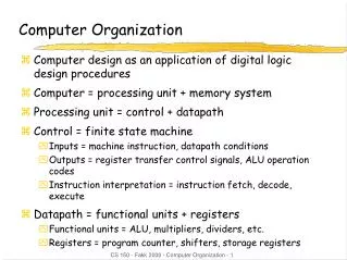
Five Components of a Computer Keyboard, Mouse Computer Devices Memory (passive) (where programs, data live when running) Processor Disk(where programs, data live when not running) Input Control Output Datapath Display, Printer
The CPU • Processor (CPU): the active part of the computer that does all the work (data manipulation and decision-making) • Datapath: portion of the processor that contains hardware necessary to perform operations required by the processor (the brawn) • Control: portion of the processor (also in hardware) that tells the datapath what needs to be done (the brain)
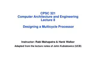
Stages of the Datapath : Overview • Problem: a single, atomic block that “executes an instruction” (performs all necessary operations beginning with fetching the instruction) would be too bulky and inefficient • Solution: break up the process of “executing an instruction” into stages, and then connect the stages to create the whole datapath • smaller stages are easier to design • easy to optimize (change) one stage without touching the others
Five Stages of the Datapath • Stage 1: Instruction Fetch • Stage 2: Instruction Decode • Stage 3: ALU (Arithmetic-Logic Unit) • Stage 4: Memory Access • Stage 5: Register Write
Stages of the Datapath (1/5) • There is a wide variety of MIPS instructions: so what general steps do they have in common? • Stage 1: Instruction Fetch • no matter what the instruction, the 32-bit instruction word must first be fetched from memory (the cache-memory hierarchy) • also, this is where we Increment PC (that is, PC = PC + 4, to point to the next instruction: byte addressing so + 4)
Stages of the Datapath (2/5) • Stage 2: Instruction Decode • upon fetching the instruction, we next gather data from the fields (decode all necessary instruction data) • first, read the opcode to determine instruction type and field lengths • second, read in data from all necessary registers • for add, read two registers • for addi, read one register • for jal, no reads necessary
Stages of the Datapath (3/5) • Stage 3: ALU (Arithmetic-Logic Unit) • the real work of most instructions is done here: arithmetic (+, -, *, /), shifting, logic (&, |), comparisons (slt) • what about loads and stores? • lw $t0, 40($t1) • the address we are accessing in memory = the value in $t1 PLUS the value 40 • so we do this addition in this stage
Stages of the Datapath (4/5) • Stage 4: Memory Access • actually only the load and store instructions do anything during this stage; the others remain idle during this stage or skip it all together • since these instructions have a unique step, we need this extra stage to account for them • as a result of the cache system, this stage is expected to be fast
Stages of the Datapath (5/5) • Stage 5: Register Write • most instructions write the result of some computation into a register • examples: arithmetic, logical, shifts, loads, slt • what about stores, branches, jumps? • don’t write anything into a register at the end • these remain idle during this fifth stage or skip it all together
ALU 2. Decode/ Register Read 5. Register Write 1. Instruction Fetch 4. Memory 3. Execute Generic Steps of Datapath rd instruction memory registers PC rs Data memory rt +4 imm
Datapath Walkthroughs (1/3) • add $r3,$r1,$r2 # r3 = r1+r2 • Stage 1: fetch this instruction, increment PC • Stage 2: decode to determine it is an add, then read registers $r1 and $r2 • Stage 3: add the two values retrieved in Stage 2 • Stage 4: idle (nothing to write to memory) • Stage 5: write result of Stage 3 into register $r3
reg[1]+reg[2] reg[1] 3 1 reg[2] 2 ALU add r3, r1, r2 Example: add Instruction instruction memory registers PC Data memory imm +4
Datapath Walkthroughs (2/3) • slti $r3,$r1,17 # if (r1 <17 )r3 = 1 else r3 = 0 • Stage 1: fetch this instruction, increment PC • Stage 2: decode to determine it is an slti, then read register $r1 • Stage 3: compare value retrieved in Stage 2 with the integer 17 • Stage 4: idle • Stage 5: write the result of Stage 3 (1 if reg source was less than signed immediate, 0 otherwise) into register $r3
reg[1]<17? reg[1] x 1 3 ALU 17 slti r3, r1, 17 Example: slti Instruction instruction memory registers PC Data memory imm +4
Datapath Walkthroughs (3/3) • sw $r3,17($r1) # Mem[r1+17]=r3 • Stage 1: fetch this instruction, increment PC • Stage 2: decode to determine it is a sw, then read registers $r1 and $r3 • Stage 3: add 17 to value in register $r1 (retrieved in Stage 2) to compute address • Stage 4: write value in register $r3 (retrieved in Stage 2) into memory address computed in Stage 3 • Stage 5: idle (nothing to write into a register)
reg[1]+17 reg[1] x 1 reg[3] 3 ALU 17 MEM[r1+17]<=r3 SW r3, 17(r1) Example: swInstruction instruction memory registers PC Data memory imm +4
Why Five Stages? (1/2) • Could we have a different number of stages? • Yes, and other architectures do • So why does MIPS have five if instructions tend to idle for at least one stage? • Five stages are the union of all the operations needed by all the instructions. • One instruction uses all five stages: the load
Why Five Stages? (2/2) • lw $r3,17($r1) # r3=Mem[r1+17] • Stage 1: fetch this instruction, increment PC • Stage 2: decode to determine it is a lw,then read register $r1 • Stage 3: add 17 to value in register $r1 (retrieved in Stage 2) • Stage 4: read value from memory address computed in Stage 3 • Stage 5: write value read in Stage 4 into register $r3
reg[1]+17 reg[1] x 1 3 ALU MEM[r1+17] 17 LW r3, 17(r1) Example: lw Instruction instruction memory registers PC Data memory imm +4
Peer Instruction How many places in this diagram will need a multiplexor to select one from multiple inputs? a) 0 b) 1 c) 2 d) 3 e) 4 or more
Peer Instruction How many places in this diagram will need a multiplexor to select one from multiple inputs a) 0 b) 1 c) 2 d) 3 e) 4 or more
rd instruction memory PC registers rs Data memory ALU rt +4 imm opcode, funct Controller Datapathand Control • Datapath based on data transfers required to perform instructions • Controller causes the right transfers to happen
What Hardware Is Needed? (1/2) • PC: a register that keeps track of address of the next instruction to be fetched • General Purpose Registers • Used in Stages 2 (Read) and 5 (Write) • MIPS has 32 of these • Memory • Used in Stages 1 (Fetch) and 4 (R/W) • Caches makes these stages as fast as the others (on average, otherwise multicycle stall)
What Hardware Is Needed? (2/2) • ALU • Used in Stage 3 • Performs all necessary functions: arithmetic, logicals, etc. • Miscellaneous Registers • One stage per clock cycle: Registers inserted between stages to hold intermediate data and control signals as they travel from stage to stage • Note: Register is a general purpose term meaning something that stores bits. Realize that not all registers are in the “register file”
2. Decode/ Register Read 5. Reg. Write 1. Instruction Fetch 4. Memory 3. Execute CPU Clocking (1/2) • For each instruction, how do we control the flow of information though the datapath? • Single Cycle CPU: All stages of an instruction completed within one long clock cycle • Clock cycle sufficiently long to allow each instruction to complete all stages without interruption within one cycle
2. Decode/ Register Read 1. Instruction Fetch 4. Memory 3. Execute 5. Register Write CPU Clocking (2/2) • Alternative multiple-cycle CPU: only one stage of instruction per clock cycle • Clock is made as long as the slowest stage • Several significant advantages over single cycle execution: Unused stages in a particular instruction can be skipped OR instructions can be pipelined (overlapped)
Processor Design • Analyze instruction set architecture (ISA) to determine datapath requirements • Meaning of each instruction is given by register transfers • Datapath must include storage element for ISA registers • Datapath must support each register transfer • Select set of datapath components and establish clocking methodology • Assemble datapath components to meet requirements • Analyze each instruction to determine sequence of control point settings to implement the register transfer • Assemble the control logic to perform this sequencing
Summary • CPU design involves Datapath, Control • 5 Stages for MIPS Instructions • Instruction Fetch • Instruction Decode & Register Read • ALU (Execute) • Memory • Register Write • Datapath timing: single long clock cycle or one short clock cycle per stage