Download
1 / 38
380 likes | 565 Views
Using Microcontrollers in Amateur Radio, an AZ EL Controller Application. A Presentation For The Southwest Ohio Digital Symposium Presented by Bill Erwin – N9CX January 10, 2009. Things I Hope To Leave You With. Share my experience with the rotor controller project

E N D
Using Microcontrollers in Amateur Radio, an AZ EL Controller Application A Presentation For The Southwest Ohio Digital Symposium Presented by Bill Erwin – N9CX January 10, 2009
Things I Hope To Leave You With • Share my experience with the rotor controller project • Explain why I made the choices I did • How it works • Status of the project • But more than that: • Why a microcontroller was a good choice for this project • What software development environments are all about • Tempt you to consider experimenting with microcontrollers Feel free to ask questions at any time !
Motivation For This Project • Developed an interest in LEO (Low Earth Orbit) satellites • Led to an interest in a better antenna system • Wanted to track LEOs with small beam antennas • Commercial rotors & controllers are available • Didn’t want to commit that much money at this stage of interest • Decided to use inexpensive rotors & build my own controller
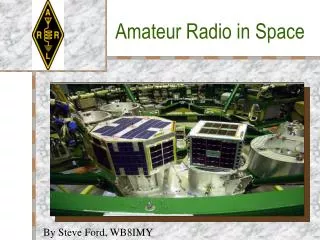
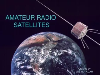
Low Earth Orbit Satellites • Basically LEOs are orbital repeaters • AMSAT has a lot of information on the WEB • LEOs offer some special challenges • They move fast. • Short contacts • Low RF power
LEO Satellites Vary In Both Size & Complexity SuitSat-1 (AO-54) Russian space suit Launched from ARISS ~355 km telemetry only temp & battery N-Cube2 10x10x10 CM I LITER VOLUME (University Projects) AO-51 (Echo) ~800 km orbit voice repeater PakSat BBS PSK31 Digital ~690 km orbit
There are a lot of “things” involved in working the LEO satellites! Computer screen Keyboard Mouse Downlink frequency Uplink frequency Doppler effects Code paddles or a microphone Azimuth of the satellite Elevation of the satellite Satellite QSOs Are Interesting!
So Many things – So Little Time! • The window for a QSO is often less than 8 minutes. • If you can automate a few “things”, your QSOs may have more “talk” time. • This project is about automating the rotors for directional azimuth & elevation antennas.
My Approach To The Project • Research the WEB for similar projects • Evaluate what I might do that is different • Understand how rotors work • Keep it (relatively) cheap • Breadboard parts of the design to verify critical assumptions • Rotor controller needs an LCD display & flashing LEDs!
Choices To Make • Features • Rotors • Software Development tools & Environment • Microcontroller
Desirable Features • Work with the Nova tracking software • Have 2 main modes: “manual” & “autotrack” • Self-calibrate to any Pulser type rotor • Remember antenna position during powerdown. • Reliable beam positioning – within 5 degrees. • Easy to update the controller software. • Minimize cost
The Rotor – You must understand the thing you are trying to control! The Alliance U100
Yes – You Can Stack Them The ability to put a pipe through the rotor body is fairly unique. Elevation Azimuth
Anatomy Of A U100 Rotor #3 Pulser Cam Physical stop tab
Anatomy Of A U100 Rotor #4 Pulsing contact Motor shaft Gear Mechanical Stop Motor Frame
Commercial Controller for the U100 Rotor 10 degree graduations on the dial
The Original U100 Rotor Schematic Diagram Rotor Control Box Simply replace this with a Microcontroller System
Model of the U100 Rotor • Strategy • Do an initial calibration to detect rotor’s pulse characteristics. • Absolute direction is known at each pulse & at rotor physical stops. • Time between pulses to estimate position of rotor to a finer degree of resolution. • Time between pulses to detect rotor limit or problems. Calibration Mode calculates: 360/ 0 Deg. 1. deg/pulse = 360 Deg/# pulse (counted) physical stop 2. tics/deg = tics/pulse / deg/pulse 3. Use physical stops as a reference ~ 100 MS // // 90 270 + Total feedback from the rotor - Note – A “tic” is 5 milliseconds 180
Block Diagram Of the Rotor Controller CW down SS relays and Phasing capacitors 15 vac Front Panel Switches CCW up EL Rotor AZ Rotor ATMEGA 16 Common Common Opto isolator Opto isolator Pulsing Contact Pulsing Contact Front Panel LEDs SS relays Phasing capacitors 15 vac Front Panel LCD 5 Volt regulator MAX 232 chip Ceramic resonator Etc. Support circuitry Note - This diagram does not indicate pin assignments
A FEW OF THE ATMEGA 16 FEATURES • THE DATA SHEET IS 358 PAGES ! • – 32 x 8 General Purpose Working Registers • – Up to 16 MIPS Throughput at 16 MHz • – 16K Bytes of In-System Self-programmable Flash program memory • – 512 Bytes EEPROM • – 1K Byte Internal SRAM • – Two 8-bit Timer/Counters with Prescalers • – One 16-bit Timer/Counter with Prescaler • – Real Time Counter with Separate Oscillator • – Four PWM Channels • – 8-channel, 10-bit ADC • – Byte-oriented Two-wire Serial Interface • – Programmable Serial USART • – Master/Slave SPI Interface • – 32 Programmable I/O Lines • YOU CAN NOT USE ALL AT SAME TIME – SHARE I/O PINS
Microcontroller – Atmel Atmega16 YOU GET A LOT OF FUNCTIONALITY IN A SINGLE PACKAGE
Microcontroller – Save Time By Buying a Proto board I use this development board for almost all of my projects. Saves a lot of soldering and cost about $17.00 I get it from “Spark Fun”.
Partial Schematic of the Rotor Controller System – Rotor interfaces Micro Controller's power supply ( +5 vdc) VCC AZ –CW PA0 (pin1) AZ –CCW PA0 (pin 2) Current limit resistor Solid State Relays (opto isolated) Front panel AZ Pulse LED \/\/\/\ X R1 2K JGC-5F X JGC-5F X < To I/O port pin |( |( )| )| 4N25 AZ – PD6 (pin20) 30 VCT xfmr 1 O O 2 rotor AZ Rotor U100 3 O O 4 x To micro controller common 15 VAC ~20 VDC Rotor common 110 VAC )| Current source for LCD Backlight R3 470 2W 15 VAC To I/O port pin 3 O O X 3 O 4 x 4N25 EL – PD7 (pin21) U100 EL Rotor O O O O 1 2 1 2 | ( To micro controller common < < X X JGC-5F JGC-5F X 2K R2 \/\/\/\ Front panel EL Pulse LED EL –UP PA2 (38) EL–DOWN PA3 (pin37) VCC
Front Panel Switches – Interface to the Microcontroller • Micro Controller Port assignments (Active low) • Port A Pin 0 - Azimuth ClockWise (CW) • Port A Pin 1 - Azimuth Counter ClockWise (CCW) • Port A Pin 2 - Elevation Up • Port A Pin 3 - Elevation Down • Port A Pin 4 - Calibrate momentary pushbutton • Port A Pin 5 - Auto Track momentary pushbutton • Port A Pin 6 - Azimuth Pulse input • Port A Pin 7 - Elevation Pulse input • LCD Port assignments (4 bit data interface) • Details are in a header file
Development Environment Fedora Core 7 GNU/LINUX With AVR-GCC tool chain Write/debug source code Program flash memory using “avrdude” utility Debug data Serial port Rotor control cable Novacomm1 protocol Windows – running NOVA
Features On My Rotor Control Box ON-OFF-ON 2X16 BACKLIGHTED LCD N.O. Pushbutton SPST N.O. Pushbutton ON-OFF-ON Indicates rotor pulse
A Look Under The Hood Xfmr for controller board Programming header Controller Board Fuse holder PWR cord connector Serial in from PC Serial out for debug Front Panel Rotor power Rotor wires plug In here. Phasing caps/SS relay boards
A Few Software Statistics • ATMEGA 16 Controller • 16KBytes Flash (Program) memory • 512 Bytes of EEPROM • 1 K SRAM • Software Sizes • Program 13394 Bytes • Data 262 Bytes – Initialized read only data • BSS 399 Bytes – initialized read/write data • Total 13995 Bytes • 30 source files • All source is written in “C” • AVR-GCC Tool Chain programs
High Level Software Design • BACKGROUND processing every 5 milliseconds • Watch every switch in the system • Monitor & debounce every switch in the controller • Advertise debounced state to the FOREGROUND processing • Maintain software timers • Decrement every interrupt (5 ms) • FOREGROUND processing • Manage a simple “state machine” based on operating modes: • Calibrate • Initialize • Manual • Auto • Manages the front panel LCD display & LEDs • Fault detection/recovery strategy
Performance Of The Controller • Used successfully in last two Field Days • Sensitive to drag on the beams – coax • False detection of physical stop or obstruction • Dressing the coax better resolved this • Have changed “late pulse” detection parameters • Be sure the beams are oriented properly before raising the mast <Hi Hi> • I consider it a success but it has not seen extensive use
Things Left Undone • Need to get a better schematic in electronic form • Scattered around in a notebook now • Finish the front panel • Print another front panel template and put plastic over it • Need to paint the box • Understand other Pulser rotors better (AR-22) • Mainly for azimuth rotor use • Motor power requirements may not be compatible • Adapt to “Potentiometer” type rotors - Perhaps • Made some accommodations, but didn’t finish this • A few things in the software to clean-up
Closing Thoughts About Antenna Rotors • Pulsers have many issues to consider • Resolution - must interpolate • Calibration process • Must have persistent memory (power-down) for AZ & EL position • Can find them reasonably priced at hamfests • Potentiometer type rotors seem less complicated • Always know where the rotor is • No persistent memory required for power-down • No interpolation required • No directional history needed • Less opportunity to get out of sync. • Nova tracking software may do most of the work for you • But – these rotors may be expensive!
FROM A SOFTWARE PERSPECTIVE • This was an interesting microcontroller project! • Microcontrollers can be used for a lot of amateur radio projects! • If you are patient and persistent you will be successful!