Download
1 / 30
340 likes | 427 Views
ACTIVE SUSPENSION TEST PLATFORM. BY. BRANDON NAYDEN & CHIAO LIU. ADVISED BY: STEVEN GUTSCHLAG. TABLE OF CONTENTS. PROJECT SUMMARY FUNCTIONAL DESCRIPTION SPECIFICATIONS BLOCK DIAGRAMS INPUTS/OUTPUTS EQUIPMENT/PARTS LIST DIVISION OF LABOR DISCUSSION OF HARDWARE/SOFTWARE

E N D
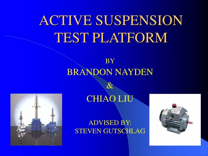
ACTIVE SUSPENSION TEST PLATFORM BY BRANDON NAYDEN & CHIAO LIU ADVISED BY: STEVEN GUTSCHLAG
TABLE OF CONTENTS • PROJECT SUMMARY • FUNCTIONAL DESCRIPTION • SPECIFICATIONS • BLOCK DIAGRAMS • INPUTS/OUTPUTS • EQUIPMENT/PARTS LIST • DIVISION OF LABOR • DISCUSSION OF HARDWARE/SOFTWARE • COMPLETED WORK • QUESTIONS
To simulate a suspension system for testing purposes. Actuator driven platform. Simulation for vehicular applications. PROJECT SUMMARY
A micro-controller controlled H-bridge will dictate the movement of the actuator platform Movement will be in a vertical fashion User input will specify desired duty cycle, direction, and waveform Digital control feedback Liquid crystal display will indicate current user desired output FUNCTIONAL DESCRIPTION
SPECIFICATIONS • Platform velocity of 7 inches/second • Platform load capacity of 200 pounds • User-friendly interface • Safe environment
INPUTS Direction Duty Cycle Waveform Displacement Position Sensor OUTPUTS Platform Movement Current user input on liquid crystal display INPUTS/OUTPUTS
EQUIPMENT LIST(HARDWARE) • DC SERVO MOTORS • IR2213 HIGH LOW DRIVERS • IRF640 TRANSISTORS • IRF350 TRANSISTORS • 4N25 OPTICAL ISOLATORS • LINEAR ACTUATOR • MICRO-CONTROLLER • RHEOSTAT
EQUIPMENT LIST(ACTUATOR) • Jack ball screw $400 ~7inches/sec @200lbs • Motor and coupling needed
DIVISION OF LABOR Chiao Liu: • Micro-controller to hardware interface • Protection circuitry • H-bridge connections • Hardware and Software debugging Brandon Nayden: • H-bridge drive circuitry • All Software modules • Hardware and software debugging
DISCUSSION OF HARDWARE 4N25 OPTICAL ISOLATORS • PROTECTION PURPOSE • VOLTAGE DRIVE FOR IR2213
DISCUSSION OF HARDWARE IR 2213 HIGH LOW DRIVER • Drive for H-bridge transistors
IR2213 Combined with H-bridge Each IR2213 drives the high and low side of H-Bridge
H-Bridge and Motor Direction Forward direction of motor H – Bridge driven by IR2213
H-Bridge and Motor Direction H – Bridge driven by IR2213 Reverse direction of motor
IR2213 Bootstrap Circuit Cbs = 10uF Cdc = .1uF
IR2213 Inputs Vdd = 18v Vss = ground H(in) = L(in) = 0 to 18v Vcc= 18v SD(shutdown)=ground Vs to load COM = ground
IR2213 Outputs LO = 0 to 18v HO = 0 to 18v above H-bridge supply
HARDWARE TESTING IR2213 switching H-Bridge
HARDWARE TESTING IR2213 switching H-Bridge
DISCUSSION OF HARDWAREPower CalculationsIRF640 120V motor 4 amp motor rated current = 2.4 W Without heat sink • Delta T ~ 149 degrees C With heat sink • Delta T ~ 53 degrees C
SOFTWARE DISCUSSION • 14 Modules • Timer 2 Mode 0 • External interrupts for port 4 output • Liquid crystal display and keypad implementation • Feedback input from actuator • Digital control system
COMPLETED WORK • Searched for appropriate linear actuator and platform configuration • Searched for appropriate motor and motor drive • All hardware design and implementation • Initial software design and implementation
COMPLETED WORK • Bi-directional actuator movement • User interface for actuator control • Display of current direction and duty cycle
COMPLETED WORK • Forward and reverse direction • Various duty cycles • Position feedback allows actuator to change direction without user input
TASKS ‘NOT’ COMPLETED • Hardware implementation with 120 volt DC motor • Build Test Platform with appropriate linear actuator • Digital control software implementation - Ensures proper output at various loads