Download
1 / 6
60 likes | 77 Views
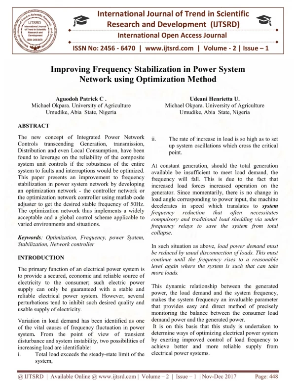
This study presents the modelling and dynamic simulation of a high penetration wind diesel power system (WDPS) consisting of a diesel generator (DG) and a wind turbine generator (WTG). First the WDPS architecture and the models of the WDPS components are described. The WDPS is simulated in wind-only (WO) mode where the DG is not running and the WTG supply active power and in wind-diesel (WD) mode where both DG and WTG supply power. The simulation results are given showing graphs of the main electric variables in the WDPS (system frequency and voltage and active power in each component). Pitch angle controller is proposed which enables the wind turbine to regulate its active power in order to retain the frequency within prescribed limits. The pitch angle control enables the WT to smooth the load and wind power variations, so that the isolated system power quality is improved. The results shows that the WDPS incorporating pitch angle controller gives better results in terms of frequency regulation. Rakesh Saini | Ankush Bhardwaj"Suppression of frequency fluctuations in Hybrid Power System using Pitch-Angle Controller" Published in International Journal of Trend in Scientific Research and Development (ijtsrd), ISSN: 2456-6470, Volume-1 | Issue-4 , June 2017, URL: http://www.ijtsrd.com/papers/ijtsrd142.pdf http://www.ijtsrd.com/engineering/electrical-engineering/142/suppression-of-frequency-fluctuations-in-hybrid-power-system-using-pitch-angle-controller/rakesh-saini<br>

E N D
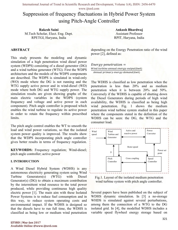
International Journal of Trend in Scientific Research and Development, Volume 1(4), ISSN: 2456-6470 www.ijtsrd.com Suppression of frequency fluctuations in Hybrid Power System using Pitch-Angle Controller Rakesh Saini Ankush Bhardwaj Assistant Professor RPIT, Haryana, India M.Tech Scholar, Elect. Eng. Dept. RPETGI, Haryana, India ABSTRACT This study presents the modeling and dynamic simulation of a high penetration wind diesel power system (WDPS) consisting of a diesel generator (DG) and a wind turbine generator (WTG). First the WDPS architecture and the models of the WDPS components are described. The WDPS is simulated in wind-only (WO) mode where the DG is not running and the WTG supply active power and in wind-diesel (WD) mode where both DG and WTG supply power. The simulation results are given showing graphs of the main electric variables in the WDPS (system frequency and voltage and active power in each component). Pitch angle controller is proposed which enables the wind turbine to regulate its active power in order to retain the frequency within prescribed limits. The pitch angle control enables the WT to smooth the load and wind power variations, so that the isolated system power quality is improved. The results show that the WDPS incorporating pitch angle controller gives better results in terms of frequency regulation. KEYWORDS: Frequency regulation; Wind-diesel; pitch angle controller; active power depending on the Energy Penetration ratio of the wind power [2], defined as: ?????? ??????????? = ???? ??????? ?????? ?????? ??????(??ℎ) ?????? ??????? ?????? ??????(??ℎ) The WDHS is classified as low penetration when the penetration is less than 20% and as medium penetration when it is between 20% and 50%. Conversely if the WDHS is capable of shutting down the Diesel Generators during periods of high wind availability, the WDHS is classified as being high wind penetration. Fig. 1 shows the medium penetration wind turbine system studied in this paper where the components stated in the definition of the WDHS can be seen: the DG, the WTG and the consumer load. Active and reactive power Power Converter Wind speed Wind Turbine and Generator Rotor speed Power set point β Cross coupling Pitch Controller Speed Controller I. INTRODUCTION A Wind Diesel Hybrid System (WDHS) is any autonomous electricity generating system using Wind Turbine Generators(s) Generator(s) (DG) to obtain a maximum contribution by the intermittent wind resource to the total power produced, while providing continuous high quality electric power [1]. The main aim with these Isolated Power Systems is to reduce fuel consumption and in this way, to reduce system operating costs and environmental impact. If the WDHS is designed so that the diesels have to run full time, the WDHS is classified as being low or medium wind penetration (WTG) with Diesel Fig.1. Layout of the isolated medium penetration wind turbine system with pitch angle controller. Several papers have been published on the subject of WDHS dynamic simulation. In [3] a no-storage WHDS is simulated against several perturbations, among them the connection of a WTG to the DG isolated grid. In [4], the modelled WDHS includes a variable speed flywheel energy storage based on 321 IJTSRD | May-Jun 2017 Available Online @www.ijtsrd.com
International Journal of Trend in Scientific Research and Development, Volume 1(4), ISSN: 2456-6470 www.ijtsrd.com hydrostatic transmission. In [5], the simulated high penetration WDHS has a DG with a clutch which allows disengaging the Diesel Engine (DE) from the synchronous machine (SM) when the generated wind power exceeds the consumed load power. This paper focuses on the dynamic simulation of a medium penetration WDHS and the dynamic improvement that produces to include a BESS in the system. After this introductory Section I, this article is organized as follows: Section II presents the control system that has been used, Section III shows the modelling of the WDHS components, Section IV presents the WDHS response against different perturbations like variations in wind speed and variations in load, those produces fluctuations in frequency and finally Section V emphasizes the effectiveness of using the pitch-angle control. the turbine can be controlled. If the Cp-γ performance characteristic is available, the turbine parameters can also be modeled from data fields containing the group of curves derived from measurement or from calculation or analytical function. The groups of power coefficient and tip speed ratio curves obtained by measurement or by computation can also be approximated in closed form by non-linear functions. The block diagram of the pitch angle controller is shown in Fig. 2. Subtracting command Wr from output power Wr1 gives output power error e that evaluates command β via pitch angle control system. Output speed wr is smoothed by hydraulic servo system that is driving blade and frequency fluctuations are dependent on speed of synchronous generator so frequency deviations get reduced. output speed pitch angle II. PITCH ANGLE CONTROL When a generator reaches rated power, the turbines must limit the mechanical output power feeding to the generator. This is required because the generator reaches the rated power at for instance 12 m/s while the maximum speed is around 25 m/s for a wind turbine. The pitch angle is controlled to keep the generator power at rated power by reducing the angle of the blades. By regulating, the angle to be on the off stalling, fast torque changes from the wind will be reutilized. Gen. spee d erro r β βref PI Wind Rate Pitch servo Rated speed Fig.3. Calculation of pitch angle β Normal blade pitch angle adjustments, within the range of 0 to 45 degrees under normal operating conditions, are carried out usually with rotational speeds of about 5-10º/s . The output power Pa, developed by wind turbine with blade radius ‘r’ can be expressed as under: ??= ? ?????C?(λ,β)V? ? (1) III. Modelling of Different components WDHPS The wind-diesel hybrid power system, under study in this work, is shown in fig. 3, where, a 300 KVA synchronous generator coupled with a diesel engine and a wind turbine driven 275 KVA induction generators are connected in parallel to feed power to the fixed load of 175 KW and three section of variable load of each 125 KW. The loads used here are purely resistive type. The diesel engine driven synchronous generator is incorporated with voltage regulator which maintains the system voltage within limits. As the induction generator cannot generate reactive power, a capacitor bank of 25 KVAR is used to provide reactive power. where, ??? is the rotor swept area, C? is the power co- efficient, λ is the tip speed ratio, β is the pitch angle while Vw being the wind speed. The tip speed ratio λ can be described as: ?? ?? (2) Pitch angle control is the most common means to control the aerodynamic power generated by the wind turbine rotor. Pitch angle control also has an effect on the aerodynamic loads which may be controlled by the controller to achieve lower torque peak as well as lower fatigue loads. The variation of CP with the pitch angle β for various values of the tip speed ratio γ. Thus, by varying the pitch angle, the power coefficient can be changed and the power captured by ? = 322 IJTSRD | May-Jun 2017 Available Online @www.ijtsrd.com
International Journal of Trend in Scientific Research and Development, Volume 1(4), ISSN: 2456-6470 www.ijtsrd.com Wind turbine output power is controlled by pitch- angle controller. Whenever the wind speed increases beyond the limit of wind turbine pitch angle controller comes in to the action. When the wind speed is less than the normal speed then pitch angle is maintain to the lowest possible angle so that maximum power can be extracted from the wind. Fig. 3. Schematic layout of wind diesel hybrid power system. The MATLAB/Simulink model of the proposed system is implemented and shown in the fig. 4 for the validation of pitch angle controller. The ratings of the different components of the HWDPS are given in the appendix-A. Fig. 4. MATLAB/Simulink model of the proposed system. 323 IJTSRD | May-Jun 2017 Available Online @www.ijtsrd.com
International Journal of Trend in Scientific Research and Development, Volume 1(4), ISSN: 2456-6470 www.ijtsrd.com With wind speed variations, the output power of the wind generator also varies and in that event the diesel generator supplies smooth power to the load to maintain frequency constant. smoother than a step variation. The base wind speed is taken as 12 m/sec. and the wind speed is initially set at 12 m/sec. After t = 10 sec, the wind speed is changed to 14 m/sec, then it is again reduced to 12 m/sec at t = 20 sec. Fig. 5 shows the wind speed variation pattern as used for simulation. The variations in the load are also shown in fig.6. As the wind speed varies there is change in the output power of the wind turbine driven IG. More the wind speed more will be the power output of the wind turbine. This can be depicted in fig. 7. As the wind speed increases the wind turbine driven IG power also increases and to balance the load and supply, the diesel engine driven SG reduces its output power, this will also reduce the operating cost of the system. The waveform of diesel engine driven SG is shown in fig. 8. The current speed, in per unit, of the diesel engine acts as input and the mechanical torque, in per unit, is the output to regulate the diesel engine so that it attains its reference value. The diesel engine is modeled and simulated with the help of a gain relating fuelling rate to torque, restricting the lower and upper torque limits to 0 and 1.1 per unit respectively, and a dead time. A second order system is used to realize the actuator whereas; the speed regulator is realized with PID control. The pitch angle control scheme regulates the wind turbine output power to its rated value by positioning the blades of the wind turbine by adjusting the pitch angle during strong windy conditions. The error signal input to the PI pitch angle controller is derived as the difference between generator rotor speed (ωg) and the reference value. The output of the pitch angle controller is the reference pitch angle, βref. It helps reduce the operating efficiency of the turbine so as to minimize power coefficient so that the generator is able to maintain its control speed value.Pitch servos are utilized for appropriate positioning of the blades, and a first order delay system is used to model the same. Because the pitch actuation system cannot respond instantly, therefore, introduction of servo delay of 0.024 s became necessary. The actuation speed is yet another parameter which restricts the working of the pitch actuation system, for which a rate limiter of ±2°/s is introduced to model the pitch angle control system more realistically. In this study, the load is also varied to check the pitch angle controller effect. As the load increases the total load is supplied by the IG and SG, this cause the increase in SG output power, as the IG is running at its full limit. The frequency variations with and without pitch angle controller is shown in fig. 9. Form the fig, 9 it can be clearly seen that when pitch angle controller comes in to the action, the frequency variations are less as compared to the system when no pitch angle controller is used. Fig. 5. Wind speed variations IV. Results and discussion The HWDPS is not connected to the grid, so the system has to overcome the power imbalance itself due to intermittent wind speed and variable load. The system is subjected to both types of perturbances i.e. variable wind speed and variable load. The base wind speed is taken as 12 m/sec. When the wind speed exceeds this value pitch angle controller comes in to action. Various simulation runs were carried out on the wind-diesel hybrid power system under the effect of multiple step changes in wind speed and the system performance is evaluated with and without pitch angle controller. However, in a real system, the speed variations are not sharp like step changes but are Fig.6. Load variations (KW). 324 IJTSRD | May-Jun 2017 Available Online @www.ijtsrd.com
International Journal of Trend in Scientific Research and Development, Volume 1(4), ISSN: 2456-6470 www.ijtsrd.com kVA Wind Turbine Generator (WTG) WTG rated power, PT-NOM = 275kW WTG Inertia constant, HWTG =2s References [1]Wind/Diesel Systems Architecture Guidebook, American Wind Energy Association,2011. [2]S. Drouilhet, High penetration AC bus wind– diesel hybrid power systems, Village Power’ 2008 Technical Workshop, Washington DC, Octubre 2008. [3]E. Muljadi, H.E. McKenna, Power quality issues in a hybrid power system, IEEE Trans. Ind. Appl. 38 (3) (2002) 803–809. [4]C. Carrillo, A. Feijóo, J. Cidrás, Comparative study of flywheel systems in an isolated wind plant, Renew. doi:10.1016/j.renene.2008.06.003. [5]R. Sebastián, R. Pe˜na Alzola, Effective active power control of a high penetration wind diesel system with a Ni–Cd battery energy storage, Renew. Energy 35 doi:10.1016/j.renene.2009.11.029. [6]J.L. Rodriguez Amenedo, J.C. Burgos Diaz, S. Arnalte Gomez, Sistemas eólicos de producción de energía eléctrica, ISBN: 9788472071391, Madrid 2003. [7]R. Hunter, D. Infield, S. Kessler, J. de Bonte, T. Toftevaag, B. Sherwin, M. Lodge, in: Hunter, Eliot (Eds.), Designing a System. Wind–Diesel Systems: A Guide to the Technology and Its Implementations, Cambridge University Press, UK, 1994 (Chapter 4). [8]K.C. Divya, Jacob Østergaard, Battery energy storage technology for power systems – an overview, Electr. Power Syst. Res. 79 (4) (2009) 511–520, doi:10.1016/j.epsr.2008.09.017. Fig.7. Active power generated by WTG Fig.8. Active power generated by diesel generator. Energy, 2008, Fig.9. Frequency variations with and without pitch angle controller. V. Conclusions The main focus of this paper is given to the control the frequency variations when the WDHS is subjected with perturbances like variable wind speed and variable load. The PI controller based pitch angle controller is designed and implemented to reduce the frequency variations. With the application of pitch angle controller the frequency variations are reduced and system performance increases. The operating cost is also reduced as the diesel engine driven SG shre of power production is reduced. (5) (2010) 952–965, The system performance can further be increased by using artificial intelligence use for tuning the parameters of PI regulator of pitch angle controller. The simulations are MATLAB/Simulink. implemented in Appendix-A Isolated Power System Rated frequency, f NOM =60Hz Rated voltage (rms, phase to phase) = 480V Diesel Generator (DG) DG inertia constant, HDG = 1.75 s Synchronous machine rated power, PSM-NOM = 300 325 IJTSRD | May-Jun 2017 Available Online @www.ijtsrd.com
International Journal of Trend in Scientific Research and Development, Volume 1(4), ISSN: 2456-6470 www.ijtsrd.com [9]S.M. Muyeen, R. Takahashi, T. Murata, J. Tamura, H. Ali Mohd, Application STATCOM/BESS for wind power smoothening and hydrogen generation, Electr. Power Syst. Res. 79 (2) (2009) 365–373, doi:10.1016/j.epsr.2008.07.007. [10]W. Lawrenz, CAN System Engineering, Springer, 1997. [11]The MathWorks, Inc., Simulink (built upon Matlab), Online http://www.mathworks.com/access/helpdesk/help/ toolbox/simulink/. [12]The MathWorks, Inc., “SimPowerSystems”, Simulink (built upon Matlab) Block Library Online http://www.mathworks.com/access/ helpdesk/help/toolbox/physmod/powersys. of Documentation, Documentation, 326 IJTSRD | May-Jun 2017 Available Online @www.ijtsrd.com