Download
1 / 6
60 likes | 67 Views
The Proton Exchange Membrane Fuel Cell (PEMFC) is an electrochemical device and its performance depends on the operating and design parameters. In this paper, optimization of design parameters like flow channel design, number of flow path, channel depth and width, cross section of the flow channel and operating parameters as operating pressure, temperature, relative humidity, mass flow rate of the reactant gases and stoichiometric ratio of the reactants on serpentine flow channel of 36 cm2 effective area of the PEMFC was considered. Creo software used for modeling and CFD software packages used for analysis of PEMFC. The optimization was done by Taguchi method using Minitab 17 software. Based on the optimization study, the Landing to Channel width ratio (L: C) - 1:2 has produced maximum power density of 0.276 W/cm2 also square of response factor (R2) was achieved by Taguchi method as 96.9%. Dr.V.Lakshminarayanan"Optimization of 36cm2 Effective Area on Serpentine Flow Channel of PEMFC" Published in International Journal of Trend in Scientific Research and Development (ijtsrd), ISSN: 2456-6470, Volume-1 | Issue-4 , June 2017, URL: http://www.ijtsrd.com/papers/ijtsrd1183.pdf http://www.ijtsrd.com/engineering/mechanical-engineering/1183/optimization-of-36cm2-effective-area-on-serpentine-flow-channel-of-pemfc/drvlakshminarayanan<br>

E N D
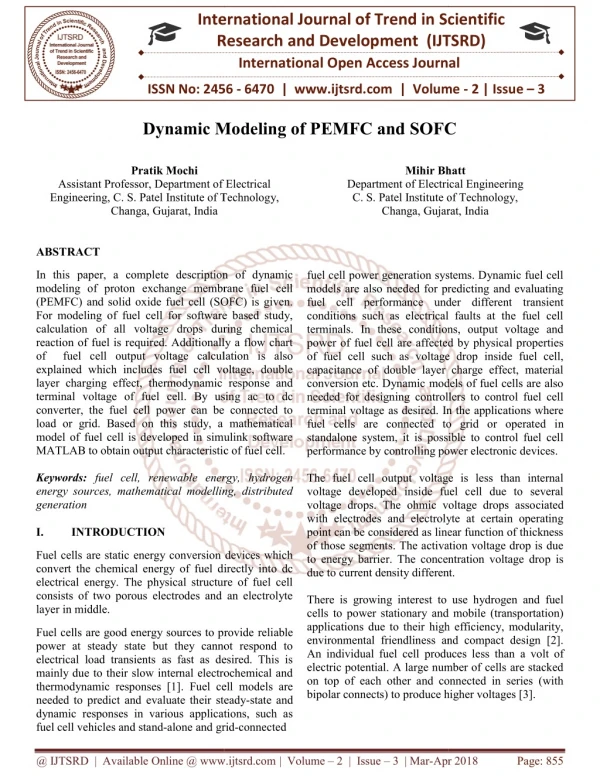
International Journal of Trend in Scientific Research and Development, Volume 1(4), ISSN: 2456-6470 www.ijtsrd.com Optimization of 36cm2 Effective Area on Serpentine Flow Channel of PEMFC Dr.V.Lakshminarayanan Department of Mechanical Engineering, B V Raju Institute of Technology, Narsapur, Telangana, India ABSTRACT The Proton Exchange Membrane Fuel Cell (PEMFC) is an electrochemical device and its performance depends on the operating and design parameters. In this paper, optimization of design parameters like flow channel design, number of flow path, channel depth and width, cross section of the flow channel and operating parameters as temperature, relative humidity, mass flow rate of the reactant gases and stoichiometric ratio of the reactants on serpentine flow channel of 36 cm2effective area of the PEMFC was considered. Creo software used for modeling and CFD software packages used for analysis of PEMFC. The optimization was done by Taguchi method using Minitab 17 software. Based on the optimization study, the Landing to Channel width ratio (L: C) - 1:2 has produced maximum power density of 0.276 W/cm2 also square of response factor (R2) was achieved by Taguchi method as 96.9%. solid electrolyte membrane placed between an anode and a cathode. The electrochemical reaction produces electric current along with water and heat as byproducts. To attain high current, peak power density, proper temperature distribution and optimum water management the various flow channel design was used. S. Simple [2] addressed in his study that the performance of PEMFC has been influenced by the flow channel path length and the flow field design with 1.2,2 stoichiometric ratios, inlet temperatures were 70°C and 80°C, operating pressure was 1.01bar in the anode and the cathode respectively. operating pressure, [1]The numerical analysis on six different cross-sections of the flow channel parallelogram 14o, parallelogram 26o, trapezium and inverted trapezium having 1.25 cm2 effective area of single pass PEMFC Lakshminarayanan et al [3]. It was concluded that, square flow channel had a peak power density of 1.133 W/cm2. Nicholas S. Siefert [4] concluded his study that the serpentine channels are very effective to get rid of the liquid because of its high gas velocity. The performance enhancement of the combined effect of operating and design parameters (operating pressure, temperature and inlet mass flow rate of reactant gases and rib to channel width ratio) of single pass serpentine and interdigitated flow channel with 25 cm2 active area of PEMFC carried out by Lakshminarayanan and Karthikeyan [5]. The results revealed that the maximum power density of interdigitated flow channel with landing to channel width 1:2 showed better performance than the serpentine flow channel with same design parameter. The various operating temperature, pressure, reactants on anode and cathode flow rate has been investigated with triangular channel geometry on 25 cm2 active area of PEMFC by Khazaee et al. [6]. The results showed that an increase in the inlet temperature of reactants, cell temperature and inlet pressure can enhance cell performance of the PEMFC. The effects of like square, triangle, were carried out by KEYWORDS Taguchi method, Design Parameters, Operating Parameters, Optimization, Serpentine Flow Channel I. INTRODUCTION The environmental impacts of non-renewable power sources and energy scarcity in many countries, focuses on renewable energy development. The Polymer Electrolyte Membrane fuel cells are environmentally friendly power source which is suitable for powering both portable devices and mobile application due to their high energy density and lower operating temperature range viz, 30oC - 70oC.It is Eco-friendly power source which is suitable for poweringboth portable devices and mobile application due to theirhigh energy density and lower operating temperature range [1]. In this paper the performance enhancement of fuel cell by optimizing the influence of various operating and design parametersusing CFD Fluent 14.0 and MATLAB software packages. The PEMFC consists of polymer parameters like cell 481 IJTSRD | May-Jun 2017 Available Online @www.ijtsrd.com
International Journal of Trend in Scientific Research and Development, Volume 1(4), ISSN: 2456-6470 www.ijtsrd.com interdigitated flow channel with traditional flow channel, the effects of the flow area ratio and the baffle-blocked position of the interdigitated flow field on the performance of PEMFC were examined experimentally by Yan et al [7]. The results concluded that, the cell performance can be enhanced with an increased inlet flow rate of reactant and cathode humidification temperature. The increasing of inlet pressure improved the consumption of reactants and more homogeneous distribution. The effect of channel design also changed the consumption of reactants and consequently increases water production by Zeroual et al. [8]. Hydration of membrane in the PEMFC is to maintain the performance. If it is not maintained properly, flooding and dehydration would occur which will affect the fuel cell performance [9, 10]. So identifying the proper channel and flow field design is a very important task while designing the fuel cell which also affects the performance of fuel cell significantly [11]. It is clearly indicated that immediate attention is required for optimizing the simultaneous influence of operating and design parameters for the performance of the PEM fuel cell. Hence this paper has a detailed study about the optimization of operating pressure, temperature, stoichiometric ratio of inlet reactant mass flow rate and various rib to channel width (L:C)-1:1,1:2, 2:1& 2:2 on serpentine flow channel of 36 cm2 active area of PEM fuel cell are to be studied and influence their performance are compared. Fig.1.Various landing to channel width ratio (a) 1:1 (b) 1:2 (c) 2:1 and (d) 2:2 of serpentine flow channel of 36 cm2 active area of PEMFC The modeling was done by creating all individual parts of the PEMFC and the dimensions of individual parts such as the anode and cathode GDL, solid polymer electrolyte membrane, the anode and cathode catalyst layers as shown in the Table 1. The various geometrical models (L: C-1:1, 1:2, 2:1 and 2:2) of serpentine flow channel were meshed by using ICEM 14.5. II. MODEL DEVELOPMENT Three dimensional (3-D) PEM fuel cell model with serpentine flow channel of various rib to channel width configurations were created by Creo Parametric 2.0 as shown in Fig.1 After geometry modeling, the next step was discretization of PEMFC used by ANSYS 14.5 ICEM software. The Cartesian grid meshing method was used, which is used in the formation of hexahedral mesh to attain accurate results. Split block method used for blocking. Body fitted mesh was used and projection factor was set to 1. The projection factor determines how closely the edges of the mesh match up with the grid. 482 IJTSRD | May-Jun 2017 Available Online @www.ijtsrd.com
International Journal of Trend in Scientific Research and Development, Volume 1(4), ISSN: 2456-6470 www.ijtsrd.com was set to anode and cathode reference concentration, Anode and cathode exchange coefficient was set to be 2. The Reference diffusivity of H2, O2 and H2O was set to as 3E-5. S. No Part Name Zone Type Thickness Length Width (mm) (mm) (mm) Taguchi method has been used to find out the most optimum combination among the input parameters which would result in getting the maximum possible output which cause the performance enhancement of PEM fuel cell. In Taguchi method L16 standard orthogonal array with 4-level and 4 factors was used and the parameters were considered as low, high and medium range values. When this orthogonal array was used, significance of factors and optimum combination can be found in 16 runs itself. The factors considered for the analysis were landing to channel ratios on serpentine flow field design (L: C- 1:1, 1:2, 2:1 and 2:2), pressure (1, 1.5, 2 and 2.5 bar), temperature (313, 323, 333 and 343 K), anode and cathode reactants as stoichiometric ratios (S/F) of 3, 3.5, 4 and 4.5. The theoretical value of hydrogen in the anode side was 4.33E-07 kg/s and oxygen in the cathode side was 3.33E-06 kg/s. Anode & Cathode Flow channel Anode & Cathode catalyst Membrane 60 60 10 Solid 1 0.08 Fluid 2 0.127 Fluid 3 4 GDL anode & cathode 0.3 Fluid Table 1.Dimensions and Zone type, assigning of fuel cell The simulation of PEMFC was solved by simultaneous equations like conservation of mass, momentum, energy, species concentration, butler– Volmer equation, Joule heating reaction and the Nernst equation to obtain reaction kinetics. The model used to consider the system as 3-D, steady state and inlet gases as ideal condition, system as an isothermal and flow as laminar, fluid as incompressible, thermo physical properties as constant and the porous GDL, two catalyst layers and the membrane as an isotropic. III. RESULTS AND DISCUSSION As per L16 orthogonal array, the inputs were given to the Ansys CFD Fluent analysis software and having all other parameters constant. The power densities for all 16 runs, obtained from analysis software and the corresponding Signal/Noise (S/N) ratios were found from MINITAB 17 software as shown in the Table 3. The rib to channel width ratio of 1:1 for serpentine flow field has shown maximum power densities of 0.263 W/cm2 and minimum power densities of 0.19 W/cm2respectively. Similarly for L:C of 1:2 and 2:1 having maximum power density of 0.276 W/cm2 and 0.199 W/cm2 respectively. The minimum power densities for the same L:C ratios have 0.221W/cm2 and 0.152 W/cm2 respectively. A control volume approach based on commercial solver FLUENT 14.5 was used to solve the various governing equations. Three-dimensional, double precision and serial processing were used for this model. The species concentration on anode side of H2, O2, and H2O were 0.8, 0, and 0.2 respectively. Similarly, on the cathode side were 0, 0.2 and 0.1 respectively. The porosity at anode and cathode side was 0.5. Open circuit voltage was set at 0.95 V on the cathode and the anode was grounded. The cathode voltage has been varied from 0.05 V to 0.95 V used for solving kinetics reaction in order to get the current flux density, H2, O2, and H2O fractions along with the flow field design. Multigrid settings were modified as F-Cycle for all the equations and entered termination restriction value was set as 0.001 for H2, O2, H2O and water saturation. The electric and proton potential values were set at 0.0001. Stabilization method BCGSTAB was selected for H2, O2, H2O, water saturation, electric and proton potential. The Anode and Cathode reference current density was set to be 10000 A/cm2 and 20 A/cm2 respectively 0.1 kmol/m3 For the rib to channel width ratio of 2:2 has shown maximum power density of 0.215 W/cm2 and minimum power density of 0.107 W/cm2. The optimization was performed for “Larger the Better” type of Taguchi method since power output of PEM fuel cell must be maximized. The S/N ratio plot for the same were obtained using MINITAB 17 software and the corresponding maximum S/N ratio gives better performance as analyzed based on larger the better as shown in the Fig.3 483 IJTSRD | May-Jun 2017 Available Online @www.ijtsrd.com
International Journal of Trend in Scientific Research and Development, Volume 1(4), ISSN: 2456-6470 www.ijtsrd.com It was concluded that the design parameter such as, rib to channel ratio of serpentine flow channel having -1:2 as L2, and the operating parameters like pressure - 2.5 bar as M4, temperature - 333 K as N2, Stoichiometric ratio of inlet mass flow rate - 4.5 as O4 were the optimum parameters to show the better PEMFC performance. The optimization results of various parameters were based on S/N ratios and the significance of each factor by ranking them according to their performance. Delta value of each factor available on the MINITAB 17 software itself was shown in Table 4. RunL:C Pressure Temperature Stoi.Ratio Power Density (W/cm2) S/N Ratio 1x1 1 323 333 3 0.190 0.213 -14.4235 -13.4159 1 2 1.5 3.5 2 343 353 333 323 353 343 343 353 323 333 353 343 333 323 4 0.238 0.263 0.221 0.236 0.273 0.276 0.179 0.199 0.152 0.170 0.107 0.128 0.215 0.196 -12.4805 -11.6141 -13.0974 -12.5599 -11.2913 -11.1769 -14.9336 -14.0028 -16.3448 -15.3893 -19.4454 -17.8464 -13.3547 -14.1664 -14.096 3 4 5 6 7 8 9 2.5 4.5 1x2 1 4 1.5 4.5 2 3 2.5 3.5 4.5 2x1 1 1.5 4 10 11 12 13 14 15 16 2 3.5 2.5 3 2x2 1 3.5 1.5 3 2 4.5 2.5 4 Average S/N Ratio Table 3. Factors, levels, power density and S/N ratio for 16 runs of optimization Fig .3. Mean S/N ratio plot for L:C (L1-L4),Pressure (M1-M4),Temperature (N1-N4), Stoi.Ratio (O1-O4) The factor with highest delta value indicates higher significance factor. It was found that pressure was the predominant factor affecting the performance of PEMFC. The other parameters were also influencing the performance to a considerable extent such as, landing to channel width ratio of serpentine flow channel, stoichiometric ratio of inlet mass flow rate and operating temperature respectively. 484 IJTSRD | May-Jun 2017 Available Online @www.ijtsrd.com
International Journal of Trend in Scientific Research and Development, Volume 1(4), ISSN: 2456-6470 www.ijtsrd.com Factors Level 1 -12.98 Level 2 -12.03 Level 3 -15.17 Level 4 -16.2 Delta 4.17 Rank 1 Landing to Channel width (L:C) Pressure (bar) -15.48 -14.46 -13.37 -13.09 2.39 2 -14.37 -13.81 -14.11 -14.09 0.56 4 Temperature (K) -14.74 -15.1 -13.44 -13.12 1.98 3 Stoichiometric ratio Table 4. Mean S/N ratios, Delta and Rank for each level of factors The percentage contribution of individual parameters, P-test and F-test on the serpentine flow fields for the performance of PEMFC has been shown in the Table 5. It has been observed from the Table 5, operating pressure has been contributed to be 43.5 % , operating temperature was 0.72 %, the stoichiometric ratio of the reactants and L:C has contributed 8.72 % and 26.3 % respectively of the PEMFC performance Factors Pressure Temperature Stoichiometric ratio L:C Pressure & Temperature Pressure & L:C Error Total DOF 2 2 2 3 1 Sum of squares 0.006704 0.000043 0.001466 0.006171 0.000074 Variance 0.003352 0.0000215 0.000733 0.002057 0.000074 F-test 88.71 27.26 19.39 5.4 0.22 P-Test 0.283 0.566 0.825 0.036 0.428 Contribution (%) 43.50 0.72 8.72 26.30 0.02 3 2 15 0.003672 0.000151 0.035937 0.001224 0.0000755 0.007537 0.81 141.8 0.059 2.197 15.24 5.50 100 Table 5.The percentage contribution of individual parameters of serpentine flow channel Also the combined effect of combination of pressure with temperature and pressure with L:C has shown 0.02 % and 15.24 % respectively contributing to peak power performance of the PEMFC. REFERENCES [1] Manso, A. P., Garikano, X., Mujika, G. M., Marzob, F.F., Barranco, J. "Influence of geometric parameters of the flow fields on the performance of a PEM fuel cell. A review."International Journal of Hydrogen Energy. 37, pp. 15256-15287. 2012. CONCLUSION The combined effect of all the parameters exhibited a different response compared to their individual effects. The maximum power density of optimizing the four different parameters on serpentine flow channel of 36 cm2 active area of PEM fuel cell using Minitab 17 provides 0.276 W/cm2 from L:C-1:2 with 2.2 bar operating pressure, 343 K temperature and 3.5 stoichiometric ratio of inlet reactant gases and R2 value was arrived 96.9 %. The effect of operating and design parameters was affecting the performance of PEM fuel cell considerably. [2] Shimpalee, S., Greenway, S., Van Zee, J. W. "The impact of channel path length on PEMFC flow-field design." Journal of Power Sources. 160, pp. 398-406. 2006. [3] Muthukumar M, Senthilkumar A P, Kavin B, Kavyaraj A, ‘Numerical investigation of performance studies on single pass PEM fuel cell with various flow channel design’, Applied Mechanics and Materials, Vols. 592-594 , pp 1672-1676, 2014. Lakshminarayanan V, Karthikeyan P, [4] Siefert, N. S., Litster, S. "Voltage loss and fluctuation in proton exchange membrane fuel cells: 485 IJTSRD | May-Jun 2017 Available Online @www.ijtsrd.com
International Journal of Trend in Scientific Research and Development, Volume 1(4), ISSN: 2456-6470 www.ijtsrd.com The role of cathode channel plurality and air stoichiometric ratio." Journal of Power Sources. 196(4), pp. 1948-1954. 2011. [8] Benmoussa,H.;Bouguettaiaa,H.(2012). study of the effect of the inlet pressure and the height of gas channel on the distribution and consumption of reagents in a fuel cell (PEMFC), Energy procedia, 18, 205-214. Zeroual,M.; BelkacemBouzida,S. ; Numerical [5] Optimization of Flow Channel Design and Operating Parameters on Proton Exchange Membrane Fuel Cell Using Mat lab. PeriodicaPolytechnica Chemical Engineering.Budapest Univ Technology Economics. 2016, 60, 3; 173-180. Lakshminarayanan V &Karthikeyan P. [9] Xianguo Li, Imran Sabir&Jaewan Park. (2007) „A flow channel design procedure for PEM fuel cells with effective water removal‟, Journal of Power Sources, 163, pp 933-942. [6] Khazaee, I, Ghazikhani, M &Mohammadiun, M , 'Experimental and thermodynamic investigation of a triangular channel geometry PEM fuel cell at different operating conditions', ScientiaIranica, vol. 19, no. 3, pp. 585-593, 2012. [10]Chi-Young Jung, Chi-Seung Lee & Sung-Chul Yi.(2008) „Computational analysis of transport phenomena in proton exchange membrane for polymer electrolyte fuel cells‟,Journal of Membrane Science,309,pp1-6. [7] Chen F. 'Effects of operating conditions on cell performance of PEM fuel cells with conventional or interdigitated flow field, Sources,2006, 162, no. 2; 1157-1164. Yan WM, Chen CY, Mei SC, Soong CY & [11] AtillaBıyıkoglu. Review of proton exchange membrane fuel cell models, International Journal of Hydrogen Energy,2005, 30, 1181 – 1212. Journal of Power 486 IJTSRD | May-Jun 2017 Available Online @www.ijtsrd.com