Download
1 / 10
100 likes | 108 Views
Wire. Input. Gas Pipe. End. Connector. Cooling Water. Aluminum Cover. P.S. Bus Bar. Superlayer Cross Section Frontend Enclosure. Front End Board (16 channels). HV cap Board. Signals from chamber wires go to HV cap board to be ground referred via 470 pF capacitors.

E N D
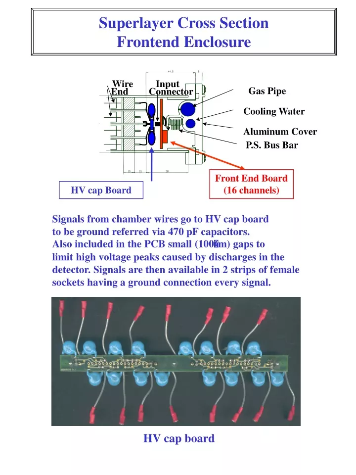
Wire Input Gas Pipe End Connector Cooling Water Aluminum Cover P.S. Bus Bar Superlayer Cross Section Frontend Enclosure Front End Board (16 channels) HV cap Board Signals from chamber wires go to HV cap board to be ground referred via 470 pF capacitors. Also included in the PCB small (100m) gaps to limit high voltage peaks caused by discharges in the detector. Signals are then available in 2 strips of female sockets having a ground connection every signal. HV cap board
Frontend Boards Frontend board 2 strips of male pins collect signals from HV cap board ; after protection circuitry they are processed by MAD ASICs and the results are available at the connector in the center of the board through which power supplies are also carried. The small connector in the lower left corner is used for the slow control bus (1 flat cable for all the boards of 1 superlayer). Fingersprings provide ground connection to the cover and heatsinking for the ASICs. A double distribution of test pulses allows electric test and simulation of traces at different positions for trigger monitor. Input for this function can be one of the two vertical strips of sockets in the upper left and right corner.
Connections to Readout 1 fine pitch flat cable (40 wires) connects each FE board to a feedtrhu PCB glued at the external of the cover. From here signals go to readout electronics through the blue connector. The smaller flat cable is used for the 4 additional signals of the 20 channel version of the FE board. The feedthru PCB is connected to the power supply bus bar via the small board soldered to the flex jumper and feeds the FE board through the signal flat cable. 2 Polyfuses (1 per supply) limit excess current. Feedthru PCB and output connector
Connections to monitors One small board per superlayer acts as an interface for Slow Control: it buffers I2C bus and provides predecoding function to address all of the FE boards. It is glued to the cover of the superlayer in the same way as the PCB of the output connectors. Slow Control interface Test pulse distribution is made with small splitter boards where impedance matching is accurately cured. External signal comes to an MCX connector placed on a small feedthru board on the cover of the superlayer. Here it’s split on 2 cables going to other 2 small boards each one placed across 2 FE boards in the upper corner. In this way 1 external signal serves 4 boards.
Mock Up 1 Frontend bd. (old version) Superlayer frame Test Pulse splitter bd. Out connector feedthru Lodgement of P.S. bus bar Slow Control Interface Output & P.S. flat cable Slow Control bus bar Superlayer cover 180o open
Mock Up 2 (test pulse) 4 frontend boards Test Pulse input connector and splitter Test Pulse splitter bd. Test Pulse splitter bd.
Mock Up 3 (bus bar) Connection from chamber wire to HV cap board Flex jumper from bus bar to out conn Test pulse cables Power Supply bus bar I2C predecoding bus
Mock Up 4 (closed superlayer top view) Connection from chamber wire to HV cap board Output flat cable bended P.S. conn DIN M/2 Test Pulse MCX conn Slow control interface Output connector Gas outlet
Mock Up 4 (closed superlayer bottom view) Output connector Water Outlet Gas Outlet HV cap board P.S. bus bar Slow Ctrl bus
Mock Up 4 (closed cover) Power Supply connector Output connectors for 20ch FE board