Download
1 / 53
530 likes | 614 Views
Physics Laboratory. UNITED STATES DEPARTMENT OF COMMERCE National Institute of Standards and Technology Gaithersburg, MD 20899-0001. UNITED STATES DEPARTMENT OF COMMERCE National Institute of Standards and Technology Gaithersburg, MD 20899-0001.

E N D
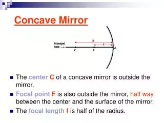
Physics Laboratory UNITED STATES DEPARTMENT OF COMMERCE National Institute of Standards and Technology Gaithersburg, MD 20899-0001 UNITED STATES DEPARTMENT OF COMMERCE National Institute of Standards and Technology Gaithersburg, MD 20899-0001 Calibration of Concave 106Ru Applicators at NIST Christopher G. Soares Ionizing Radiation Division National Institute of Standards and Technology
History 1937 Fialla builds first extrapolation chamber 1947 Beta-ray applicators in use 1952 Amersham makes first metal foil sources 1953 Loevinger benchmark paper on extrapolation chambers 1976 Establishment of NBS calibration service by Pruitt & Loevinger 1988 Publication of serious discrepancy between NBS and Amersham 1990 Reestablishment of revised NIST calibration service by Soares 1996 Establishment of the UW calibration service by DeWerd 1997 ICRU Report Committee for medical betas formed 1998 First international dosimetry intercomparison for applicators 200? Establishment of national standards at NPL and PTB
300 mm long air path 30 mm diameter collecting electrode 10 mm diameter source Ocular Therapy 10 mm diameter source 4 mm diameter collecting electrode in contact or at 1 mm in tissue-equivalent plastic 1 mm source in TE plastic block 1 mm diameter collecting electrode in contact with block surface Extrapolation Chamber Measurement Geometries Protection Level Brachytherapy
Extrapolation Chamber Measurements of Beta-Particle Sources Source Geometry Application 1 sigma near point 10s cm in air protection +2% planar mm in tissue ocular therapy +6% seed/line mm in tissue brachytherapy +10%
Collecting electrode Insulating gap Current pA Air gap, mm Extrapolation Chamber Schematic Electrometer 79.54 pA Air gap=0.40 mm Water-equivalent plastic High-voltage electrode/window Source Ionization
Collecting electrode Insulating gap Current pA Air gap, mm Extrapolation Chamber Schematic Electrometer 69.73 pA Air gap=0.35 mm Water-equivalent plastic High-voltage electrode/window Source Source Ionization
Collecting electrode Insulating gap Current pA Air gap, mm Extrapolation Chamber Schematic Electrometer 59.82 pA Air gap=0.30 mm Water-equivalent plastic High-voltage electrode/window Source Source Ionization
Collecting electrode Insulating gap Current pA Air gap, mm Extrapolation Chamber Schematic Electrometer 49.85 pA Air gap=0.25 mm Water-equivalent plastic High-voltage electrode/window Source Source Ionization
Collecting electrode Insulating gap Current pA Air gap, mm Extrapolation Chamber Schematic Electrometer 39.89 pA Air gap=0.20 mm Water-equivalent plastic High-voltage electrode/window Source Source Ionization
Collecting electrode Insulating gap Current pA Air gap, mm Extrapolation Chamber Schematic Electrometer 29.92 pA Air gap=0.15 mm Water-equivalent plastic High-voltage electrode/window Source Source Ionization
Collecting electrode Insulating gap Current pA Air gap, mm Extrapolation Chamber Schematic Electrometer 19.95 pA Air gap=0.10 mm Water-equivalent plastic High-voltage electrode/window Source Source Ionization
Collecting electrode Insulating gap Current pA Air gap, mm Extrapolation Chamber Schematic Electrometer 9.99 pA Air gap=0.05 mm Water-equivalent plastic High-voltage electrode/window Source Source Ionization
Aeff=14.68 mm2 Aeff=0.648 mm2 1.2 mm 4 mm 0.6 mm NIST Medical Extrapolation Chamber Collecting Electrodes
d [ ]0 k’ k I() d . (W/e) Sair medium . D(z0) = 0 A D(z0) absorbed dose rate in medium at depth z0 (W/e) average energy to create an ion pair (33.97 J/C) Sair stopping power of medium relative to air (1.12) 0 air density at reference conditions (1.197 kg/m3) A area of the collecting electrode (14.68 mm2) I() net current at air gap [ ]0 slope of current vs air gap function at zero air gap medium k’ product of corrections which are independent of air gap k product of corrections which vary with air gap Extrapolation Chamber Dose Equation
Determination of Net Current I+,- = C(U2-U1)/t I= (I+ + |I-|)/2 C the external feedback capacitance U1,2 initial and final voltages on the feedback capacitor t integration time
Corrections to Measured Current for Near Geometry Measurements Constant during the extrapolation curve measurement: k’ba difference in electron backscatter between collector and tissue Varying during the extrapolation curve measurement: kTp correction to reference conditions of temperature and pressure kre correction for recombination losses kdi correction for radiation field divergence
Near Geometry Divergence Effect Less side losses with decreasing air gap
Extrapolation Chamber with 1 mm Electrode Planar 90Sr/Y Reference Source Well-Type Ionization Chamber Radiochromic Film Calibration Chain at NIST Extrapolation Chamber with 4 mm Electrode Reference Line Source Source to be Calibrated
ICRU Report Committee: Dosimetry of Beta Rays and Low Energy Photons for Brachytherapy with Sealed Sources Commission Sponsors: R. Caswell A. Wambersie Committee: W.G. Cross H. Järvinen (Chairman) C.G. Soares S. Vynckier K. Weaver Consultant: D. Flühs Committee Charter: Collection of existing data New intercomparison of dosimetry of ophthalmic applicators
Participants in the Measurement Comparison National Institute of Standards & Technology USA Chris Soares National Physical Laboratory UK Tudor Williams Radiation and Nuclear Safety Authority Finland Hannu Järvinen Catholic University of Louvain, St.-Luc Hospital Belgium Stefaan Vynckier Algemeen Ziekenhuis Middelheim Belgium Bob Schaeken University Hospital of Essen Germany Dirk Flühs
Field Parameterization D(z,r) = D(z0,r0) [D(z,r0)/D(z0,r0)] {D(z,r)/D(z,r0)} D(z0,r0) = reference absorbed dose z0 = 1 mm r0 = 0 mm [D(z,r0)/D(z0,r0)] = relative central-axis depth dose {D(z,r)/D(z,r0)} = relative off-axis dose
Detectors Used for the Measurements Effective Meas. Phys. Detector Inst. thickness Covering Diam. Diam. Application Extrap. Chamb. NIST 0 0.0016 PET 0.91 500 1,2 4.32 Extrap. Chamb. NPL 0 0.0016 PET 4 140 1 GAF films NIST 0.007 0 >0.1 >1 1,2,3 0.0017 0 GAF film STUK 0.007 0 3 >1 1 TLDs UCL 0.3 0 5 5 1,2 1.0 0 Alanine AZM 1.2 0 4.9 4.9 1,2 Scintillator NIST 0.4 0.2 PE 1 6 1,2,3 Scintillator Essen 1 0.02 Al 1 2.55 2,3 Silicon diode STUK 0.05 0.375 PMMA 4 7 2 Diamond STUK 0.3 0.65 PS 0.5 7.1 2 Ion chamb. STUK 0 0.03 PET + 3 61 2 0.2 water . All dimensions in mm Applications: 1= Reference dose rate; 2=Relative central axis depth dose; 3=Relative off axis dose
Source Geometries 1 cm 90Sr planar 106Ru planar 106Ru concave
Typical Source Profiles Tracerlab & ICN/Tracerlab New England Nuclear Atlantic Research Corp/Atomchem 3M Technical Operations Isotope Products Lab/Nucl. Assocs. Amersham International Manning Research
Calibrated Average Dose Rate 170 mGy/s Peak Dose Rate 230 mGy/s
Results of Reference Dose Rate Determinations Extrap. Extrap. GAF GAF 0.3mm 0.3mm 0.4mm 1mm 1.2mm Chamb. Chamb. Film Film TLD diamond scin TLD alanine Source (NIST) (NPL) (NIST) (STUK) (UCL) (STUK) (NIST) (UCL) (AZM) 90Sr 0.237 0.260* 0.229 0.258 0.248 --- 0.278 0.308 0.272 NEN Gy/s Gy/s Gy/s Gy/s Gy/s Gy/s Gy/s Gy/s 0258 106Ru 1.61** 1.82** 1.62 1.63** 1.40 1.99 1.69 1.75 1.49 BEBIG mGy/s mGy/s mGy/s mGy/s mGy/s mGy/s mGy/s mGy/s mGy/s planar 106Ru --- --- 2.48 2.10*** 2.55 3.17 --- 2.79 2.89 BEBIG mGy/s mGy/s mGy/s mGy/s mGy/s mGy/s mGy/s mGy/s mGy/s concave *from a contact measurement with a factor of 0.573 applied to correct to 1 mm ** from a contact measurement with a factor of 0.742 applied to correct to 1mm ***from a measurement at 1.2 mm with a factor of 1.082 applied to correct to “
Depth Dose Measurements of a 90Sr Ophthalmic Applicator Gradient at 1 mm: 6.5% per 0.1 mm
Depth Dose Measurements of a 90Sr Ophthalmic Applicator Gradient at 1 mm: 6.5% per 0.1 mm
Depth Dose Measurements of a Planar 106Ru Ophthalmic Applicator Gradient at 1 mm: 3% per 0.1 mm
Depth Dose Measurements of a Planar 106Ru Ophthalmic Applicator Gradient at 1 mm: 3% per 0.1 mm
Depth Dose Measurements of a Curved 106Ru Ophthalmic Applicator Gradient at 1 mm: 2% per 0.1 mm
Depth Dose Measurements of a Curved 106Ru Ophthalmic Applicator Gradient at 1 mm: 2% per 0.1 mm
Spread in Measurement Results Source Contact 1 mm 2 mm 3 mm 4 mm 5 mm 7 mm 10 mm 90Sr 6.2% 9.6% 5.3% 3.4% 4.8% 8.8% --- --- NEN (10) (8) (10) (10) (9) (9) 0258 106Ru 5.5% 10.5% 4.0% 6.1% 6.4% 6.8% 10% 19% BEBIG (8) (9) (8) (8) (8) (8) (7) (7) planar 106Ru 8.2% 14% 4.8% 6.9% 7.3% 7.0% 9.4% 18% BEBIG (8) (6) (8) (8) (8) (8) (8) (8) concave All percentages are single standard deviations. Yellow values are for reference absorbed dose rate; white values are for relative central-axis dose.
t z+t D(z) dz D(z) z Davg(t,z) = t z z+t Effective Point of Measurement The depth of an infinitely thin detector that gives the same dose rate as that averaged over a detector of finite thickness, t If the gradient is constant across the detector, then the effective point of measurement is in the center. Otherwise, calculate and find the value of zwhich gives the value Davg(t,z) in the function D(z).
Measured Off-Axis Dose Function for the 90Sr/Y Planar source Essen scintillator NIST radiochromic film NIST EGS4 calculation
Measured Off-Axis Dose Function for the 106Ru/Rh Planar source Essen scintillator NIST radiochromic film NIST EGS4 calculation
Measured Off-Axis Dose Function for the 106Ru/Rh Concave source Essen scintillator NIST radiochromic film NIST EGS4 calculation
CCB CCX CIB Applicator Types Studied
Sample of Off Axis Dosimetry Measurements for CIB Source Along Non-Cutout Ordinal Radii
Sample of Off Axis Dosimetry Measurements for CIB Source Along non-cutout ordinal radii Dose rate, mGy/s Along cutout ordinal radius Radial distance, mm
An Attempt to Make a Depth Dose Curve Independent of Source Type plot dose rate per unit activity density
Electrometer 9.99 pA A Curved-electrode Extrapolation Chamber? use the applicator as the high-voltage electrode