Download
1 / 30
340 likes | 656 Views
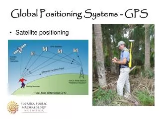
DIFFERENTIAL GPS AND AUGMENTATION SYSTEMS. Colin Ford March 2012. Introduction. Problem… Civilian GPS positioning accuracy is ~5 meters horizontally due to uncertainty in the satellite clocks, ephemerides and atmospheric delays

E N D
DIFFERENTIAL GPS AND AUGMENTATION SYSTEMS Colin Ford March 2012
Introduction • Problem… • Civilian GPS positioning accuracy is ~5 meters horizontally due to uncertainty in the satellite clocks, ephemerides and atmospheric delays • Currently GPS does not provide enough integrity for safety of life (SOL) requirements • Thus, GPS isn’t accurate enough and doesn’t have enough integrity for some applications, such as automatically landing Unmanned Aerial Vehicles (UAVs), docking ships, precision aircraft approach and landings, etc • Solution… • Improve the GPS positioning accuracy and system integrity! • How? • Using Differential GPS and Augmentation techniques and methods
Augmentation Systems • Augmentation means that the GNSS signals are augmented by additional information and signals to improve Integrity and Accuracy • Why augmentGNSS? • GPS has very low inherent integrity • Data message is fixed length and inflexible • System warnings about faulty satellites can take 10’s of minutes to be incorporated • Unsuitable for Safety-of-Life applications, such as landing commercial airliners • GPS L1 accuracy is compromised by system errors • Ephemeris inaccuracy, Troposphere/Ionosphere effects
Augmentation Systems (cont.) • What augmentation systems are available? • Ground Based Augmentation Systems (GBAS) • Examples: DGPS, LAAS, JPALS, GRAS, RTK, pseudolites • Typically local or regional, distances 10 – 100km • Provide a rapid response to local users for increased integrity • Continuous, real-time monitoring and broadcast of corrections • Typical position accuracy improved to < 3 meters (with carrier-phase measurements accuracy improved to centimeters) • Space Based Augmentation Systems (SBAS) • Examples: WAAS, EGNOS, MSAS, GAGAN • Provides corrections over a broader region • Possible to inform the users within 6 seconds on problems that occur with the GPS system for improved integrity • Typical position accuracy improved to < 3 meters
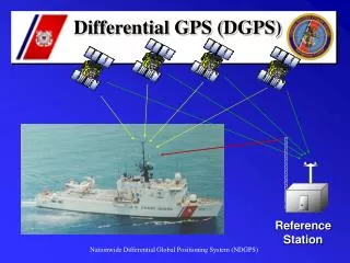
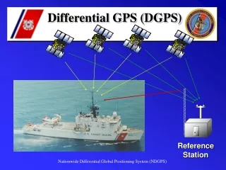
Differential GPS (DGPS) GPS Satellites Xuser, Yuser, Zuser PR and ΔPR Corrections Xmeas, Ymeas, Zmeas PR Error GPS Receiver Xactual, Yactual, Zactual Measured – Actual = Error
DGPS Details • Both user and reference receiver measurements are temporally and spatially correlated • Thus, DGPS techniques can effectively remove the uncertainties of satellite clock and ephemeris • Atmosphere may be correlated depending upon the ionosphere activity and locations within the troposphere • Correlations improve as the user gets closer to the reference • Range of corrections can be up to 100 km • Any multipath is uncorrelated • Corrections are typically applied in real-time, but susceptible to transmission latencies which can affect performance • DGPS can also be used for providing carrier-phase measurements in real-time for centimeter accuracy to support Real-Time Kinematic (RTK) testing
GBAS • Based on the DGPS concept of a system at a known location providing corrections to a user to augment the users Global Navigation Satellite System (GNSS) navigation solutions • The receivers have to be capable of receiving and applying these corrections • What corrections? How often? What format? …. • Thankfully there are some standards! • RTCM (RTCM SC-104) • LAAS (DO-224)
RTCM • Radio Technical Committee for Maritime (RTCM) SC-104 standard • Specifies the code and carrier correction data messages for DGPS applications • RTCM messages are commonly used by DGPS and RTK systems for transmitting correction data to users • There are different ‘Types’ of RTCM messages, some common ones are: • Type 1: Code differential corrections • Type 3: Reference station information • Type 9: Similar to Type 1 • Types 18-19: RTK Carrier corrections • Types 20-21: RTK PR corrections
RTCM Example (from SimGEN) Measured * - Truth = Correction Range Rate correction Carrier Phase correction * Note: This value is corrected for declared clock errors (af0, af1, af2)
LAAS • Local Area Augmentation System (LAAS) is another application of DGPS defined in Interface Control Document (ICD) RTCA/DO-246B • Ground-based system, intended for use at airfields being developed by the FAA to ultimately permit Category III GPS precision approach and landings • Uses GPS monitoring stations and a broadcast station for complete airport coverage of accurate DGPS corrections and integrity information to aircraft within 20-30 miles of the airport GPS Satellites Monitoring Stations LAAS Broadcast Station
LAAS VHF Broadcast • Similar to the RTCM standard, LAAS utilizes up to 5 message types for augmenting GPS around the airport • The primary message types are: • Type 1: Differential corrections data, time of validity, error estimates, etc • Type 2: GBAS related data, numbers of monitor stations installed, tropospheric data, monitor station locations, effective range for valid operation • Type 4: Final approach data, airport ID, approach category, runway number/letter, threshold height, glide path angle • All messages have CRC error detection VHF Data Broadcast
SBAS • Provides satellite and ionosphere corrections over a wide region for increasing GNSS navigation accuracy and integrity • Examples are: • Wide Area Augmentation System (WAAS) – North America (Operational 2003) • European Geostationary Navigation Overlay Service (EGNOS) – Europe (Pre-Operational) • MTSAT Satellite-based Augmentation System (MSAS) – Asia (Operational 2007) Ref: www.esa.int
SBAS (cont.) • The requirements for the receiver to use these messages are specified in DO-229C (Minimum Operational Performance Standards for Global Positioning System / Wide Area Augmentation System Airborne Equipment) by RTCA, Inc. • Before WAAS, the U.S. National Airspace System (NAS) did not have the potential to provide horizontal and vertical navigation for approach operations for all users at all locations…SBAS makes this possible
SBAS (cont.) • Consists of monitoring stations and geostationary satellites located over the desired region • Monitoring stations observe and measure GPS satellite orbit and clock drift plus signal delays caused by the atmosphere and ionosphere • The computed corrected differential messages get compiled into a 250bps Navigation data message on the ground and transmitted to the SBAS satellites for relaying the message to users • Transmitted to users on L1 (1575.42 MHz) • Future provisions may support L5 (1176.45 MHz) for increased accuracy Ref: http://www.freeflightsystems.com/waas_howitworks.htm
SBAS (cont.) • Primary objectives are to determine the following for users to improve accuracy and integrity: • Integrity information, able to respond within 6 seconds of detection of an anomalous GPS satellite • Fast-changing component due to the satellite clock error • Slow-changing component due to the satellite ephemeris • Slow-changing component due to the ionosphere propagation delays for a set of points corresponding to a latitude/longitude grid Ref: www.faa.gov As a result, the FAA can guarantee both Horizontal and Vertical Protection Levels (HPL and VPL) for aircraft on their CAT1 approaches, which require a Localizer Performance with Vertical guidance (LPV) of 200 feet
SBAS (cont.) • Wide Area Augmentation System (WAAS) – North America • 38 monitoring stations • 3geostationary satellites • PRN133 (AMR) – INMARSAT 4F3 98°W • PRN135 (CRW) - Intelsat Galaxy XV 133°W • PRN138 (CRE) - TeleSatAnik F1R 107.3°W Ref: www.esa.int Ref: www.faa.gov
SBAS (cont.) • European Geostationary Navigation Overlay Service (EGNOS) - Europe • 34 monitoring stations, 4 Control Centers, 6 Navigation Land Earth Stations • 4geostationary satellites • PRN120 - Inmarsat-3-F2/AOR-E 15.5°W • PRN124 - Artemis 21.5°E • PRN126 - Inmarsat-4-F2/EMEA 25°E • PRN131 – Inmarsat-3-F1/IO 64.5°E • Astra 4B - 5°E (Scheduled for 2012) • Astra 5B – 31.5°E (Scheduled for 2013)
SBAS (Cont.) • MTSAT Satellite-based Augmentation System (MSAS) – Asia • 8 monitoring stations • 2 geostationary satellites • PRN129 – MTSAT-1R 140°E • PRN137 – MTSAT-2 145°E
Spirent’s Augmentation Capability • SBAS • WAAS, EGNOS and MSAS simulation capability supported • All SBAS signals are based on ICD RTCA/DO-229C November 28th 2001: Minimum operational performance standards for Global Positioning System/Wide Area Augmentation System Airborne Equipment • GBAS • RTCM correction messages are supported for DGPS and RTK applications • LAAS simulation is based on GNSS Based Precision Approach Local Area Augmentation System (LAAS) Signal-in-Space Interface Control Document (ICD) RTCA/DO-246B • GSS4150 Very High Frequency (VHF) transmitter for RF transmission of LAAS messages
Spirent generated DGPS corrections (RS-232) • RTCM SC-104 Simulating DGPS • With a single RF output, Spirent supports generation of RTCM DGPS and RTK corrections • The NMEA Output capability supports logging/outputof the DGPS RTCM message types 1,3, and 9 Receiver Under Test GNSS RF DGPS corrections User DGPS System
Simulating DGPS (cont.) • The RTCM definition file supports RTCM DGPS and RTK message types 1, 3, 9,16,18-22, and 58 • The corrections can be logged to a file and/or output in real-time via RS-232
Receiver Under Test Simulating DGPS (cont.) • Multiple RF outputs (from either a single chassis or multiple) support system level hardware in the loop testing • Permits testing with receiver(s) under test AND the DGPS/RTK base station receivers for generation of the necessary DGPS/RTK corrections Receiver Under Test GNSS RF GNSS RF DGPS/RTK corrections DGPS Receiver
Simulating LAAS • LAAS simulation is supported either on RS-232 or transmitted on VHF using the GSS4150 • Users can control: • Define message options (Identifier, Delays, Data errors, Format Rate) • Set broadcast frequency (108 to 117.975MHz), signal power profile • Differential Corrections • Reference Station specifics • Data errors and modification Receiver Under Test GNSS RF Corrections VHF GSS4150
Simulating SBAS • If enabled, SBAS can be transmitted on both L1 and L5 frequencies • Similar to the common GPS Constellation editor
Simulating SBAS (Cont.) • Supports definition and control of: • Monitoring stations • Message output control, interval, sequence, etc. • Navigation data errors • Navigation data modification • Signal control, latencies, covariance, degradation, etc. • SBAS satellite PRNs, locations and motion • Ionosphere errors and reference grid data
Quasi-Zenith Satellite System • The Quasi-Zenith Satellite System (QZSS), is a proposed three-satellite regional time transfer system and Satellite Based Augmentation System for the Global Positioning System • Coverage of the Asia and Pacific region • The first satellite 'Michibiki' was launched in September 2010 • Full operational status is expected by 2013 • QZSS can only provide limited accuracy on its own and is not required to work in a stand-alone mode. As such, it is viewed as a GNSS Augmentation service
Quasi-Zenith Satellite System • The satellites are to be placed in a periodic Highly Elliptical Orbit (HEO). These orbits allow the satellite to dwell for more than 12 hours a day with an elevation above 70° (meaning they appear almost overhead most of the time) and give rise to the term "quasi-zenith" for which the system is named.
Quasi-Zenith Satellite System • Signal compatible with modernized GPS signals • Transmit the L1C/A signal, L1C signal, L2C signal and L5 signal • Delivers improved positioning performance via ranging correction data provided through the transmission of submeter-class performance enhancement signals L1-SAIF (1575.42 MHz) and LEX (1278.75MHz) • Improved position accuracy ~1 meter RMS nationwide based on wide-area differential GPS technique • L1SMS for emergency warnings • Improves reliability by means of failure monitoring and system health data notifications
Summary • Differential GPS (DGPS) and augmentation systems (SBAS and GBAS) benefit users by providing increased accuracy and integrity • These systems are documented in the following standards: • (DGPS) Radio Technical Committee for Maritime (RTCM) Special Committee (SC) 104 • (LAAS) LAAS Signal-in-Space Interface Control Document (ICD) RTCA/DO-246B • (SBAS) Minimum operational performance standards for GPS/WAAS Airborne Equipment ICD RTCA/DO-229C • Spirent’s test solutions are flexible enough to support a wide array of applications and test requirements
Thank You Colin Ford