Download
1 / 38
380 likes | 386 Views
This presentation explores the use of Ground Penetrating Radar (GPR) for detecting and estimating the location of buried objects. It discusses time-reversal imaging, computational time-reversal, target detection and location estimation, and unresolved research issues in the field. The presentation also covers the use of time-reversal imaging for focusing energy on targets and the measurement and processing details involved. Computer simulations are used to model the sub-surface interface and explore the effectiveness of the proposed methods.

E N D
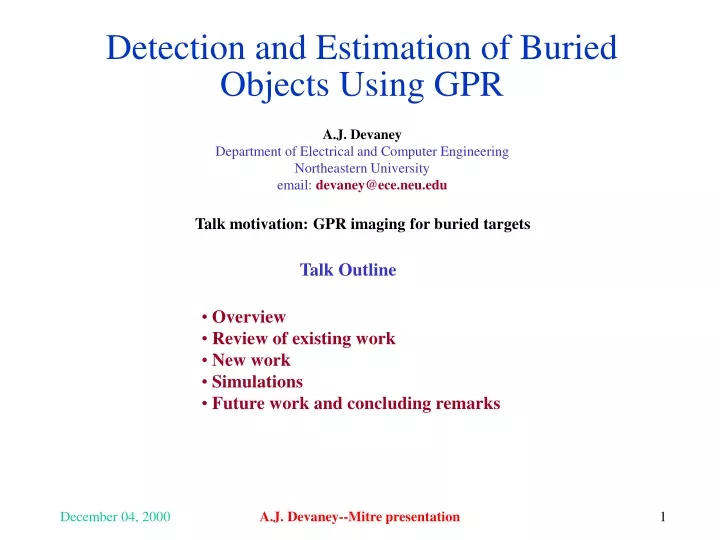
Detection and Estimation of Buried Objects Using GPR A.J. Devaney Department of Electrical and Computer Engineering Northeastern University email:devaney@ece.neu.edu Talk motivation: GPR imaging for buried targets Talk Outline • Overview • Review of existing work • New work • Simulations • Future work and concluding remarks A.J. Devaney--Mitre presentation
Intervening medium Intervening medium Intervening medium Time-reversal Imaging for GPR Goal is to focus maximum amount of energy on target for purposes of target detection and location estimation In time-reversal imaging a sequence of illuminations is used such that each incident wave is the time-reversed replica of the previous measured return First illumination Intermediate illumination Final illumination Without time-reversal compensation With time-reversal compensation A.J. Devaney--Mitre presentation
Computational Time-reversal Time-reversal compensation can be performed without actually performing a sequence of target illuminations Multi-static data Time-reversal processor Computes measured returns that would have been received after time-reversal compensation Target detection Target location estimation Return signals from sub-surface targets Time-reversal processing requires no knowledge of sub-surface and works for sparse three-dimensional and irregular arrays and both broad band and narrow band wave fields A.J. Devaney--Mitre presentation
Research Program Unresolved Issues • Scale and geometry • How does time-reversal compensation perform at the range and wavelength • scales and target sizes envisioned for sub-surface GPR? • Clutter rejection • How does extraneous targets degrade performance of time-reversal algorithms? • Data acquisition • How does the use of CDMA or similar methods for acquiring the multi-static • data matrix affect time-reversal compensation? • Phased array issues • How many separate antenna elements are required for adequate time-reversal • compensation? • Sub-surface • Can the background Green functions for the sub-surface be estimated from • first arrival backscatter data or conventional diffraction tomography? A.J. Devaney--Mitre presentation
Illumination Measurement Backpropagation Array Imaging Focus-on-transmit Focus-on-receive High quality image In conventional scheme it is necessary to scan the source array through entire object space Time-reversal imaging provides the focus-on-transmit without scanning Also allows focusing in unknown inhomogeneous backgrounds A.J. Devaney--Mitre presentation
Illumination #1 Measurement Phase conjugation and re-illumination Time-reversal Imaging Repeat … If more than one isolated scatterer present procedure will converge to strongest if scatterers well resolved A.J. Devaney--Mitre presentation
Applied array excitation vector e = K e Arbitrary Illumination Single element Illumination Single element Measurement Array output Using Mathematics Anything done experimentally can be done computationally if you know the math and physics Kl,j=Multi-static response matrix output from array element l for unit amplitude input at array element j. A.J. Devaney--Mitre presentation
Applied array excitation vector e = K e Arbitrary Illumination Array output Mathematics of Time-reversal Multi-static response matrix = K Array excitation vector = e Array output vector = v v = K e K is symmetric (from reciprocity) so that K†=K* T = time-reversal matrix = K† K = K*K Each scatterer (target) associated with different m value Target strengths proportional to eigenvalue Target locations embedded in eigenvector The iterative time-reversal procedure converges to the eigenvector having the largest eigenvalue A.J. Devaney--Mitre presentation
Processing Details Multi-static data Time-reversal processor computes eigenvalues and eigenvectors of time-reversal matrix Eigenvalues Eigenvectors Return signals from ground or sub-surface targets Standard detection scheme Location estimation using MUSIC A.J. Devaney--Mitre presentation
Multi-static Response Matrix Specific target Green Function Vector A.J. Devaney--Mitre presentation
Time-reversal Matrix Single Dominant Target Case A.J. Devaney--Mitre presentation
Intervening Medium Focusing With Time-reversal Eigenvector Image of target located at r0 Array point spread function • Need the Green functions of the medium to perform focusing operation • Quality of “image” may not be good—especially for sparse arrays A.J. Devaney--Mitre presentation
Vector Spaces Noise Subspace Signal Subspace A.J. Devaney--Mitre presentation
Music Pseudo-Spectrum Steering vector Pseudo-spectrum peaks at scatterer locations A.J. Devaney--Mitre presentation
Computer Simulation Model xn x Thin phase screen model l0 Sub-surface interface Down-going wave l1 Up-going wave x x0 z A.J. Devaney--Mitre presentation
GPR Antenna Model x z Uniformly illuminated slit of width 2a with Blackman Harris Filter A.J. Devaney--Mitre presentation
Ground Reflector and Time-reversal Matrix A.J. Devaney--Mitre presentation
Approximate Reflector Model A.J. Devaney--Mitre presentation
Earth Layer 1 A.J. Devaney--Mitre presentation
Down Going Green Function z=z0 A.J. Devaney--Mitre presentation
Future Work • Finish simulation program • Include sub-surface interface • Employ extended target • Include clutter targets • Compute eigenvectors and eigenvalues for realistic parameters • Compare performance with standard ML based algorithms • Broadband implementation A.J. Devaney--Mitre presentation