Download
1 / 1
30 likes | 282 Views
FMCW Radar to Detect Buried Objects. Neil Corbett. Introduction

E N D
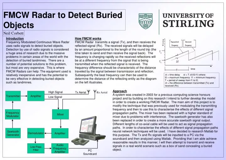
FMCW Radar to Detect Buried Objects Neil Corbett Introduction Frequency Modulated Continuous Wave Radar uses radio signals to detect buried objects. Detection by use of radio signals is considered a huge area of research due to the massive problems in certain areas of the world with the detection of buried landmines. There are a number of potential solutions to this problem, but most are very expensive. This is where FMCW Radars can help: The equipment used is relatively inexpensive and has the potential to be very effective in detecting buried objects such as landmines. How FMCW works FMCW Radar transmits a signal (Tx), and then receives the reflected signal (Rx). The received signals will be delayed by an amount proportional to the length of the round trip (the time taken to send and then receive the signal back). The frequency is changing rapidly so the received reflections will be at a different frequency from the signal that is being transmitted when the reflected signal is received. The frequency difference should be characteristic of the distance traveled by the signal between transmission and reflection. Subsequently the beat frequency can then be used to determine the distance of the reflecting entity as the diagram on the left illustrates. time ∆t = time delay ∆t = T ∆f/(f2-f1) where: f2 = maximum frequency f1 = minimum frequency T = period of sweep from f1 to f2, ∆f = the difference between transmitted (Tx) and received (Rx). Approach A system was created in 2003 for a previous computing science honours project and by building on this research I intend to further develop the model in order to create a working FMCW Radar. The main aim of this project is to modify the technique that was previously used for modulating the transmitting frequency and then to use this to characterise the effects of different signal propagation paths. The mixer has been replaced with a higher standard of mixer due to problems with interference. The sawtooth generator has also been replaced in order to create a more accurate sawtooth signal output. Different lengths of co-axial cable will be used to act as signal propagation paths. In order to characterise the effects of different signal propagation paths neural network techniques will be used. I have decided to research Matlab for this purpose. The Tx and Rx signals will be inputted to a PC via the soundcard and then analyzed using Matlab. Providing that I am able achieve reasonable results in this manner, I will then attempt to transmit and receive signals in a real world scenario such as a box of sand concealing a buried object. High Signal Tx Aerial Rx Aerial Transmitter Amplifier Low Signal Frequency Modulator Mixer Sawtooth Generator Demodulator Amplifier Low-Pass Filter Audio Frequency Amplifier PC Soundcard