Download
1 / 41
410 likes | 576 Views
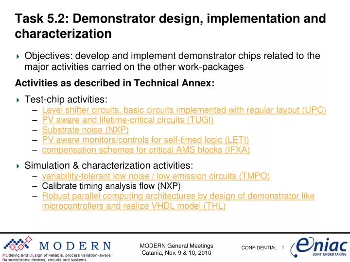
Task 5.2: Demonstrator design, implementation and characterization. Objectives: develop and implement demonstrator chips related to the major activities carried on the other work-packages Activities as described in Technical Annex: Test-chip activities:

E N D
Task 5.2: Demonstrator design, implementation and characterization • Objectives: develop and implement demonstrator chips related to the major activities carried on the other work-packages Activities as described in Technical Annex: • Test-chip activities: • Level shifter circuits, basic circuits implemented with regular layout (UPC) • PV aware and lifetime-critical circuits (TUGI) • Substrate noise (NXP) • PV aware monitors/controls for self-timed logic (LETI) • compensation schemes for critical AMS blocks (IFXA) • Simulation & characterization activities: • variability-tolerant low noise / low emission circuits (TMPO) • Calibrate timing analysis flow (NXP) • Robust parallel computing architectures by design of demonstrator like microcontrollers and realize VHDL model (THL) MODERN General Meetings Catania, Nov. 9 & 10, 2010
Task 5.2: Demonstrator design, implementation and characterization • Review MODERN General Meetings Catania, Nov. 9 & 10, 2010
Task 5.2: Demonstrator design, implementation and characterization • Purpose of demonstrators (to be aligned during WP5 meeting) • Test-chip activities: • (UPC) demonstrate on-chip sensors, level shifters, prove benefits of circuits with regular layout, digital and RF M&C? (T4.1, T4.4, T3.3) • (TUGI) develop benchmark circuits and validate aging models (T2.5) • (NXP) verify full-chip substrate analysis (T3.4?) • (LETI) verify AVFS (T3.3 timing errors, WP4control), full demo chip • (IFXA) verify M&C concepts T3.3, provide recovery/aging variations data T3.3 • Simulation & characterization activities: • (TMPO) verify variability tolerant low-noise / low-electromagnetic-emission delay-insensitive asynchronous circuits WP4 • (NXP) Calibrate timing analysis flow ??? • (THL) verify fault tolerant multi-core chip WP4 MODERN General Meetings Catania, Nov. 9 & 10, 2010
Task 5.2: Demonstrator design, implementation and characterization • Innovative aspects of demonstrators (to be clarified during WP5 meeting) • Test-chip activities: • (UPC) • (TUGI) • (NXP) • (LETI) • (IFXA) innovative M&C concepts (T3.3), novel aging test and characterization methods • Simulation & characterization activities: • (TMPO) variability tolerant circuits? • (NXP) • (THL) MODERN General Meetings Catania, Nov. 9 & 10, 2010
Task 5.2: Demonstrator design, implementation and characterization Deliverables Deliverables: • R: Basic concept verification of noise, compensation, test chip architectures (NXP, IFXA) M12 (03/2010) approved • R: Test chip simulation results, topology, implementation and evaluation strategy, VHDL models; IP block design and layout for the different technologies CMOS (digital AMS&RF), SOI, etc. and technology nodes (TMPO, NXP, IFXA, UPC,THL, LETI, TUGI) M27 (06/2011) • R: test chip characterization (evaluation to show effectiveness of PVT circuitry, of basic processing circuits implemented with regular layouts,), calibration of PV robust analysis flows (TMPO, UPC, NXP, IFXA, LETI, TUGI) M36 (03/2012) MODERN General Meetings Catania, Nov. 9 & 10, 2010
MODERN. WP5 Status - UPC MODERN General meeting Catania November 9th, 2010
UPC in relation with T5.2 • Several UPC tasks will produce output susceptible to be a demonstrator chip • T3.3 PV-aware design • Highly tolerant dgital design • monitor & control of RF • T4.1: Variability-aware design • D4.1.2 “Tape-out of prototype on-chip sensors and level shifter circuits for (self-) adaptive design.” • T4.4: Design of regular architectures for high manufacturability and yield • D4.4.2 “Tape-out of a chip based on regular transistor arrays.”
T3.3 – Tolerant redundant circuits: Turtle logic • Described in D3.3.1 (M12) • Initially inspired in probabilistic logic • Signal redundancy in all nodes • Inherently robust against logic discrepancies in complementary signals • In sequential circuits, state transition stopped when there is a discrepancy • Current status: • redundant signal sequential architecture already defined • Application example designed at gate level: multiplier 4x4 • Next steps: • Gate-level simulation and evaluation (D3.3.2) • Physical design to evaluate area, timing, power (D3.3.3)
SUPPLY COMPENSATION SUPPLY COMPENSATION THERMAL COMPENSATION T3.3 - PV monitor and tolerance • Purpose: design and implement a RF front-end tolerant to PVT variations, under the constraint of low-power consumption . • RF front-end with a Low Noise Amplifier, Mixers and auxiliary circuitry for PVT variations detection and compensation (bias circuits, detectors, control circuitry, control loops). • Thermal monitoring will be also considered as innovative detection technique of PVT variations, integrating on chip a differential temperature sensor. • Status: • Preliminary block diagram of the proposed test chip (not indicated possible on-chip sensors for Built In Test (BIT))
T4. 1 - Monitor and adaptation • ABB and AVS demonstration to control leakage or delay • Leakage depends both on VDD and VBS • Delay depends especially on VDD • Current status: • Evaluation of type of sensors • In terms of design complexity and parameter yield to improve • Relation/Potential collaboration with LETI • Sensors based on delay • At schematic/circuit only (different target technology) • Upcoming meeting to define collaboration and excahnge information
T4.4 - VCTA application for variation impact of regularity • Design of Voltage Controlled Delay Line (VCDL) and DLL
T4.4 - Jitter and mismatch • Jitter in DLL dependent on mismatch • Sources for mismatch • Random dopant fluctuations, Interface roughness, etc. • Lithography interactions between neighboring patterns • Regular design expected to present smaller jitter
T4.4 - Experiment proposal • Design regular (VCTA) and irregular layouts of DLL • If size of transistors is large enough, mismatch dominated by neighborhood effects • Design several versions with different transistor sizing • The relative importance of regularity vs random mismatch will be obtained • D4.4.2: Tape-out of chip based on regular transistor arrays (M30)
BACK Summary UPC • Designs that are well on-track • RF monitoring and compensation (T3.3) • VCTA regular impact experiment (T4.4) • Designs that need extra effort • Digital PV-aware (T4.1) • Turtle logic (T3.3) • At this point in time fully confident they can be part of T5.2 • Remarks/Questions • Technology: ST 65nm • Use of CMP reserved budget; which conditions? One chip? submission date limit?
Motivation & TechnologyTask 5.2 - TUG • The overall motivation is to verify physical reliability models including process variability reflecting the performance of MOS transistors over lifetime resulting from WP2. • The goal of Task 5.2. is to determine demonstrator circuits sensitive to the observed degradation effect in order to allow the benchmark of different aging model development approaches. • Technology: The entire work is based on austriamicrosystems AG HVCMOS technology. MODERN General Meetings Catania, Nov. 9 & 10, 2010
Status of Work Task 5.2 - TUG Verification of simple Isub based analytical model in order to support the validation of possible benchmark circuits by including the models into a reliability simulator. Elaborate approaches to incorporate the PV into the models. Close cooperation with TUV which is working on physical PV aware reliability models based on TCAD and measurement results. MODERN General Meetings Catania, Nov. 9 & 10, 2010 16
Principle of Reliability SimulatorTask 5.2 - TUG The principle of the reliability simulation is to represent the device degradation at different points in time (e.g. after 10 years) by updating specific SPICE parameters. The SPICE deck is updated via a dynamic link between the analog simulator and the reliability simulator. MODERN General Meetings Catania, Nov. 9 & 10, 2010 17
Outlook Task 5.2 - TUG Design and fabrication of benchmark structures. Validation of proposed benchmark cases. Outstanding deliverables: D5.2.2 – M27 D5.2.3 – M36 BACK MODERN General Meetings Catania, Nov. 9 & 10, 2010 18
Substrate activities for Modern Task 3.4 Sergei Kapora 29 October 2010
Neptune 314 for substrate noise studies Developed de-embedding scheme to remove contribution of IO coupling 8 digital IPs with different isolation approaches Correlation of de-embedded measurement results with 3rd-party EDA tool for full-chipsubstrate noise analysis
Neptune 5 test chip specs Current floor plan proposal Spectrum of the output of FM buffer with and without digital noise present in the system
BACK Substrate extraction flow in SOI Disturbed output of the bandgap due to noise propagation through the substrate *functionality in red isadded to the standard flow
LETI MODERN Contribution to WP5 • Contribution to WP5.2: Demonstrator : design, implementation and characterization • Status : • Design of a full chip in 32 nm : LoCoMoTIV • Full AVFS architecture • Including WP3 and WP4 IP contributions • PG tape : December • Deliverables: • D5.2.2: Test chip simulation results : on track • D5.2.3 : IP block design and layout : on track • D5.5.4 : test chip characterization : on track
A dynamic adaptive Architecture DVFS AVFS Power (mW) Period (ns) Same Speed Power supply (V) Same Power • Performances improvements: DVFS vs AVFS
Architecture Overview A fine grainLocalDynamicAdaptive voltage and frequency scaling architecture Diagnostic: Process-Voltage-Temperature Timing fault detection or prevention (WP3) Actuators: Based on Vdd-hopping Local clock generation using FLL Power/Variability Control Local control with minimum hardware (WP4) Global control : high level algorithms RunTime 0.9v 0.9v 0.7v 0.7v ANOC CVPU PE CVPU PE Main HW objective : a minimum hardware based on standard cellsand simple analog macros for flow insertion and maximum efficiency
LoCoMoTIV architecture An AVFS GALS approach at fine grain to reach an optimum energetic point according to PVT variations CVP-U NI NI NI CVP-U NI NI NI NI 16KB P-$ 16KB P-$ 16KB P-$ 16KB P-$ 32-KB TCDM 32-KB TCDM 32-KB TCDM 32-KB TCDM STxP70-V4(Rev. A) + ITC #1 STxP70-V4(Rev. A) + ITC #2 STxP70 STxP70 OCE OCE OCE OCE Local Compensation of Modern Technology Induced Variability Asynchronous NoC ITs ITs L2-RAM DMA WDT 4 XP70 µP 4 XP70 µP 4 XP70 µP 4 XP70 µP HWS S M M Dedicated memory blocks ANOC NI Memory Mapped Peripherals V/F Local actuators Timing Fault Detectors PVT sensors Hopping / FLL Hopping / FLL D-$ S PVT S PVT Local Controller CVP : Clock-Vraiability-Power Debug & Test Unit TMS TCK TDI TDO BI BO TMS TCK TDI TDO BI BO TMS TCK TDI TDO BI BO TMS TCK TDI TDO BI BO
LoCoMoTIV flooplan BACK Hopping transition and switches : Voltage genration Fully digital FLL : Frequency generation PVT probes PE1 PE0 L2RAM ANOC PE3 PE2 CDMA
MODERN General Meetings Catania, Nov. 9 & 10, 2010 Task 5.2 IFXA Objective and Outline • Objective: development and verification of monitor & control (M&C) strategies for AMS&RF circuits to deal with aging/reliability issues and aging induced parameter variations in nanometer CMOS. • Close link to T3.3 (M&C concept development) • Outline • Basic aging/reliability assessment identify sensitivities • Aging simulations (proof of sim.-concept, model-hardware correlation in T5.2) • Dedicated test-structures for transient effects and aging-parameter-variations • Development of M&C concepts T3.3 • Implementation and verification of M&C concepts • Silicon based proof of concept • Concept development for accelerated aging/stress tests T5.2 • Development of characterization methods (fast transient effects) T5.2
MODERN General Meetings Catania, Nov. 9 & 10, 2010 Task 5.2 IFXA Completed and Remaining Activities • Test-chip status: • TC #1 (32nm CMOS): taped, lab characterization completed • TC #2 (32nm CMOS): taped, lab characterization on-going • TC #3 (28nm CMOS): design on-going, tape-out end 2010 • Status basic aging/reliability assessment (-> circuit level results) • Circuit level aging simulation flow proven on TC1 (OpAmps, VCOs) • Structures for transient effects and aging-variations implemented on TC2 • VCO: aging of startup VDD • OpAmp: Offset drift • Static offset • Recovery
MODERN General Meetings Catania, Nov. 9 & 10, 2010 BACK Task 5.2 IFXA Completed and Remaining Activities • Status implementation & verification of M&C concepts • Accelerated aging test-setup proven on TC1 and TC2 (OpAmps, VCOs) • Fast offset characterization method (transient effects) proven on TC2 • Measurements to be finalized on TC2 • ADC incl. error correction (static & transient offsets) • Switch degradation monitor circuits • Variations of aging parameters • Novel burn-in concept (to increase robustness and compensate PV) • Macros to be implemented on TC3 • Switch control circuits to be implemented on TC3 • DCDC test-structures
MODERN General Meetings Catania, Nov. 9 & 10, 2010 Task 3.3 IFXA Key Results Aging Assessment • Majority of key blocks AMS & RF is inherently robust (“self-regulation”) • Sensitive cases • Non-linear / asymmetric operation (comparator) • Full scale driven devices (switches, VCO, …) • Transient effects (recovery) significantly contribute • Variations of aging parameters need to be considered ( T5.2) • Scaling 65nm to 32nm: not absolute values but sensitivities change • OpAmp: Offset drift • VCO: aging of startup VDD • Static offset • Recovery
MODERN General Meetings Catania, Nov. 9 & 10, 2010 Task 3.3 IFXA Key Results M&C Development • Switches • Monitor concepts: ring oscillator, current sensing • Control: “frequency locked loop”, analog control loop • Aging induced offsets • Avoid offset generation: e.g. chopping (comparator) • Correction of static & dynamic effects: e.g. error correction by redundancy • Burn-in: dedicated stress to increase robustness and compensate PV ADC search algorithm incl. redundancy
MODERN General Meetings Catania, Nov. 9 & 10, 2010 Task 3.3 IFXA Completed and Remaining Activities • Testchip #1 and #2 taped, samples not fully characterized, design of #3 on-going • Basic aging/reliability assessment almost completed • Simulations completed, sim.-concept verified (TC1, OpAmps, VCOs) • Structures for transient effects and aging-variations implemented on TC2 • Development of M&C concepts completed • Implementation and verification of M&C concepts ongoing • Accelerated aging test-setup proven on TC1 and TC2 • Fast offset characterization method proven on TC2 • TC2 • Switch monitor circuits • ADC incl. error correction • TC3 • Switch control circuits to be implemented on TC3 • DCDC test-structures • Concept development for accelerated aging/stress tests
MODERN General Meetings Catania, Nov. 9 & 10, 2010
MODERN General Meetings Catania, Nov. 9 & 10, 2010
MODERN General Meetings Catania, Nov. 9 & 10, 2010 BACK
MODERN WP5 THALES foreseen activities 10 November 2010
WP4 Web Meeting THL activities in MODERN linked to WP5 • Up to now we (THL) have had contributions in WP4 to develop a SystemC simulator of a predictable fault-tolerant multicore chip (based on the ISD network) with embedded middleware and operating libraries. • developed a processor tile • designed and implemented fault injection scenarios • design the multicore chip with ISD network • implemented a SystemC simulator of the chip • designed and implemented operating libraries, middleware and tools • modified in-house tools to generate parallel code for this architecture • designed, developed and implemented a video detection algorithm on top of the architecture based on the Viola & Jones face detection (Haar filters).
WP4 Web Meeting Supervisor : TILE 0 TILE N TILE 1 CTR CTR ACC ACC CTR DMA DMA DMA LMEM LMEM LMEM NIM NIM NIM Architecture (SystemC) iNoC : Internal Network OCP TL2 … ISD HyperCube Network NUMA SHMEM • CTR: ConTRoler • DMA: Direct Memory Access • NIM: Network Interface Module • (Makes network protocol translation) ACC:ACCelerator LMEM:Local MEMory SHMEM:SHared MEMory NUMA: Non Uniform Memory Access
WP4 Web Meeting Fault Scenario Definition • Memory faults: a fault occurs randomly in shared data memory (e.g. wrong value written). A read time, the memory tells the reading tile that data contains errors. This reading tile sends a message to the supervisor tile. The supervisor takes actions to solve the problem. • Tile faults: a processing tile sends periodically a message to the supervisor tile (watchdog). When it stops doing so, the supervisor takes actions to solve the problem. • To solve a problem, the supervisor : • Stops the processing tiles • Find a new memory mapping and tile mapping. • Configure the network according to that mapping. • Restart the processing tiles
Supervisor : TILE 0 CTR DMA LMEM NIM BACK WP5 foreseen activities and deadlines • WP5: multicore chip FPGA implementation • M27: D5.2.2: • VHDL IPs developed • supervisor Tile, NIM, SHMEM controler, NoC • Software developed • Tile bootloader, SHMEM test access • M36: D5.3.3 • Several Tiles (12 foreseen) • Develop HAL • Reuse Operating Libraries from SystemC • Video detection application.