Download
1 / 10
100 likes | 110 Views
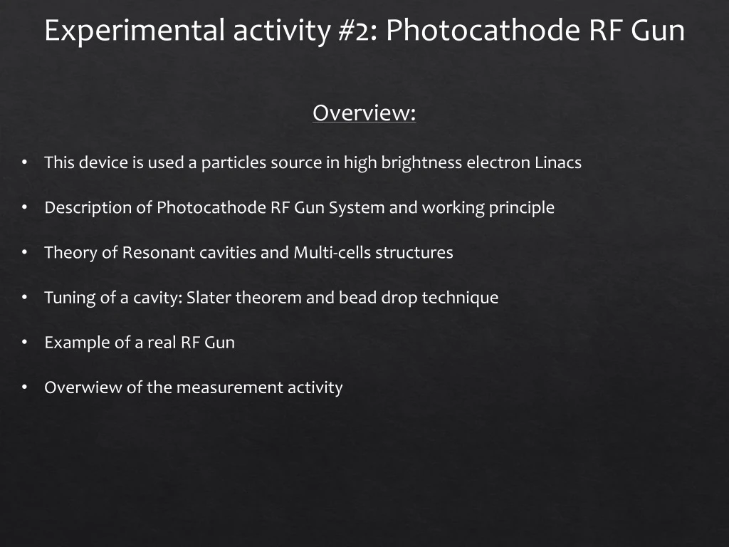
Experimental activity #2: Photocathode RF Gun. Overview: This device is used a particles source in high brightness electron Linacs Description of Photocathode RF Gun System and working principle Theory of Resonant cavities and Multi-cells structures

E N D
Experimental activity #2: Photocathode RF Gun • Overview: • This device is used a particles source in high brightness electron Linacs • Description of Photocathode RF Gun System and working principle • Theory of Resonant cavities and Multi-cells structures • Tuning of a cavity: Slater theorem and bead drop technique • Example of a real RF Gun • Overwiew of the measurement activity
Experimental activity #2: RF Photocathode Gun • An RF Gun is an electron source that generates very low emittance pulsed beams. The electron bunches are generated by photoelectric effect. • Very short laser pulses hit a metallic cathode, which is embedded in an electromagnetic accelerating structure. • It is a Standing Wave (SW) structure realized by two coupled resonant cavities. • The emitted electron bunches are confined by a solenoidal magnetic field and accelerated by an oscillating electric field on the gun axis. • Picosecond laser pulses and RF fields are synchronized for efficient acceleration. • The ratio of the number of electronsemitted per incidentphotoniscalled Quantum Efficiency (Qe) whichis a function of the photon energy. For metals, the minimum energy photons are typically in the ultravioletrange (λ(Cu) < 267nm). Master Oscillator klystron RF signal Drive Laser Solenoid Cathode Electron beam
Electric field beam Standing Wave structures: Resonant cavities • A Resonant cavity is a (almost) closed conductor enclosing an empty volume where the electromagnetic fields can only exists in the form of particular spatial conformations (resonant modes) whose components, including the accelerating field Ez, rigidly oscillate at some specific frequencies characteristic of the mode (Standing Waves). • Real cavities are lossy. Surface currents dissipate energy, so that a certain amount of RF power must be provided from the outside to keep the accelerating field at the desired level. If the external excitation is turned off, fields inside the cavity decay exponentially with a time constant characteristic of any given mode. Reflection coefficient
Cavities and multi-cell cavities • Cylindrical cavity or pillbox operating at the TM010accelerating mode.This mode has a longitudinal electric field in the centre of the cavity which is suitable for particle acceleration. • Usually to have a more efficient acceleration more cavities (N) are coupled together. • The N-cells structure obtained behaves like a system composed by N oscillators coupled together. • Each single-cell mode degenerates in a set of N possible coupled oscillation modes of the whole system, characterized by a cell-to-cell phase advance given by: • SW multi-cell cavities are designed to use the last mode (for acceleration (.
Slater Theorem For a cavity on resonance, the electric and magneticstoredenergies are equal. If a small perturbationis made on the cavitywall, thiswillgenerally produce an imbalance of the electric and magneticenergies, and the resonantfrequencywillshiftto restore the balance. The Slaterperturbationtheoremdescribes the shift of the resonantfrequency, when a small volume ΔV isremoved from the cavity of volume V. The general resultis Where U is the totalstored energy. Thistheorem can be usedalsoto measure the fieldprofilesin the cavity by inserting a perturbingobject and measuring the frequencyshiftswhilemovingitalongselectedpaths. The theoremmathematicalexpressionisdifferent in this case and formfactorsneed to be introducedbecausefieldlines are stronglydeformedin this case, whilethey are almostunperturbedwhen the boundaryisslightlydeformed.
Bead Drop Measurement Probe Network Analyzer 1-port Reflectionmeasurement Nylon wire If the perturbingobject (bead) is a perfectlyconductingsphere the values of the formfactors are: If a sphere of radius a ismovedalong the beam axis of a cavity the E fieldprofile and the R/Q of a resonantaccelerating mode can be estimatedaccording to: bead R Q Sign of the E-fieldprofile (ittakesinto account the phasevariation of the field )
ELI-NP RF photocathode gun • 1.6 cell photoinjector of the BNL/SLAC/UCLA type with new features: • elliptical shaped irises with larger aperture • Symmetric port to compensate the dipole field component • coupling hole rounded to reduce the pulsed heating • cooled cathode • fabrication without brazing using the clamping gasket technique Input Waveguide RF gun waveguide cathode Beam tube pumping port cells Solenoid Cathode
Experience overwiew RF Gun characterization in reflection with Network Analizer Calibration Localize the tworesonatingmodesmeasuring the S11 (NA settings: fstart=2.8GHz fstop=2.86GHz) Estimate the frequencyseparationbetween the twomodes. Measure the resonantfrequency and the S11|fres and compute the couplingfactorβfor the twomodes (NA settings: fcenter=fresspan=4MHz) (NOTE: the π-mode isovercoupledβ > 1, the 0-mode isundercoupledβ < 1) RF Gun characterization in transmission with Network Analizer Measure the S21 of the device and using the «Bandwidth» function (Marker Search -> Bandwidth) measure the LoadedQualityFactor QL Compute the UnloadedQualityFactor Q0 and the External QualityFactorQext Longitudinalelectricfieldprofilemeasurementwith “bead-drop” technique (mode π): Ticksdrawn on the nylon wire are equallyspacedevery 5 mm Filla spreadsheet with: bead position (z [m]) and measuredfres Compute and plot (f-fres)/fresvs z and finallyEzvs z
R/Qcalculation: From the spreadsheet, compute R/Q (Note: The spherical bead radiusis a=0.0018m, ε=8.85418781762E-12, c=299792458 m/s) Filling/Decay time measurement (time domain with realistic RF pulse) The filling or decay time, is the time for the energy stored in the cavity with loaded Q = QL to build to 1/e of its saturation point Connect the RF signal generator through a switch and an amplifier to the Gun and read the output probe through the oscilloscope 100Hz, fewuspulses 5V 15V switch scope fπ • Measure the filling time τ of the gun. Compare it with the oneevaluated from QL. • (OPTIONAL) Longitudinalelectricfieldprofilemeasurement with “bead-drop” technique (mode 0) • Repeat the procedure of point3 for the 0 mode
Useful Formulae Cavityfilling time Acceleratingvoltage on axis Unloaded Q External Q factor Loaded Q factor Couplingcoefficientβ R/Q and Acceleratingfield from the perturbationmeasurement