Download

1 / 11
130 likes | 355 Views
Grounded Grid Tube Gain Stage Basic layout Great for current output DACs like Monica DIY Paradise July 2006. Schematic Courtesy of CY Liew. Simplified Schematic diyparadise (cathode resistor is 160ohm like previous page). DC power jack (to power up Monica). This is the layout I used.

E N D
Grounded Grid Tube Gain Stage Basic layout Great for current output DACs like Monica DIY Paradise July 2006
Simplified Schematic diyparadise (cathode resistor is 160ohm like previous page)
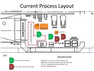
DC power jack (to power up Monica) This is the layout I used. I fitted in Monica2 together in one chassis. You could separate them but if you do so, please keep the interconnect cable between Monica2 and GG short. The layout is done this way to minimize digital noise from corrupting the analog section. The digital signal wire is preferably shielded all the way from the back to Monica2. You could place the input jack at the front if you wish. IEC socket Input digital jack (up to you to use RCA, BNC, etc) Power transformer Choke Plate choke Plate choke 5842 5842 Monica2 DAC Output RCA jack Chassis Layout Top View
The following wiring diagrams are meant to aid you in the sequence in wiring this tube gain stage. Of course, you can do it some other way. Any other way, actually. • Power supply wiring is not shown here. You don’t have to use the same scheme. Use whatever components you have in hand. • Remember basic rules still apply: • keep signal wires far away from filament wires, transformer and chokes. • also keep digital signal far away from analog signals. In fact, just keep the digital signal far away from anything. If you have to cross wires, then corss only at 90 degrees. • twist tightly the heater wires, place close to chassis. • maintain star ground. • SAFETY FIRST: REMEMBER TO SOLDER IN BLEEDER RESISTOR! REMEMBER TO “EARTH THE CHASSIS”! • You “earth the chassis” by wiring Earth of IEC socket to chassis, through a nut. THEN confirm the resistance between Earth of IEC and chassis is as close to zero as possible.
2 1 3 4 7 8 9 5 6 Output RCA jack insulated from chassis Monica2 Using tube socket spigot as ground GG power supply 5842 Ground layout
Ground the Grid pin (hence Grounded Grid) Note that 5842 has 4 grid pins, pins 4, 5, 7 & 8. It’s best to ground all of them though you could probably get away with just grounding one. Tie to tube spigot. GND (tube spigot) Signal Wiring (Grid first)
Ground the Grid pin (hence Grounded Grid) Note that 5842 has 4 grid pins, pins 4, 5, 7 & 8. It’s best to ground all of them though you could probably get away with just grounding one. Tie to tube spigot. 160 Ohm Cathode R Plate resistor or Plate choke GND (tube spigot) B+ Signal Wiring (Plate and Cathode)
Ground the Grid pin (hence Grounded Grid) Note that 5842 has 4 grid pins, pins 4, 5, 7 & 8. It’s best to ground all of them though you could probably get away with just grounding one. Tie to tube spigot. R/L analog from Monica2 160 Ohm Cathode R Plate resistor or Plate choke GND (tube spigot) B+ R/L output to RCA socket Output cap >0.33uF 250V Signal Wiring
Can’t get any 5842s? Adapt! 6688 is available for cheap! The premium brother, 7788, shares the same pin! As this is a pentode, a 47-100 Ohm resistor between plate and cathode is required, for triode operation. R/L analog from Monica2 160 Ohm Cathode R Plate resistor or Plate choke GND (tube spigot) B+ R/L output to RCA socket Output cap >0.33uF 250V 6688/E810F/7788 Signal Wiring