Download
1 / 19
190 likes | 383 Views
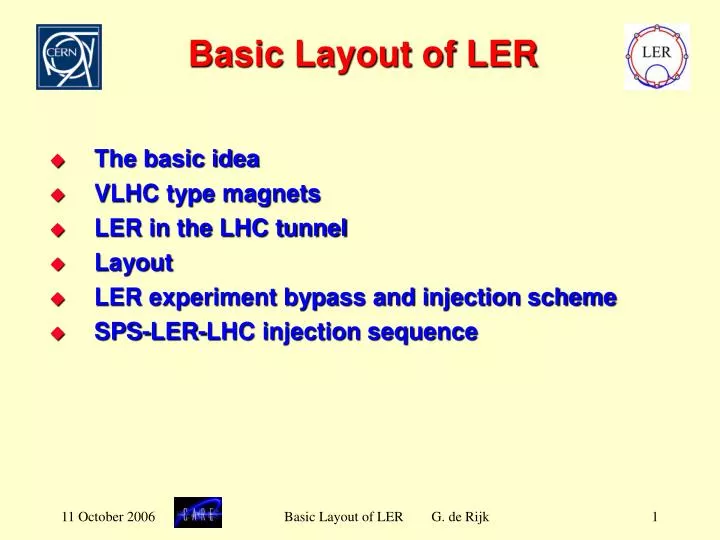
Basic Layout of LER. The basic idea VLHC type magnets LER in the LHC tunnel Layout LER experiment bypass and injection scheme SPS-LER-LHC injection sequence. The basic idea. LER is a two beam machine Two-in-one superferric combined function magnets Inject beam from SPS into LER

E N D
Basic Layout of LER • The basic idea • VLHC type magnets • LER in the LHC tunnel • Layout • LER experiment bypass and injection scheme • SPS-LER-LHC injection sequence Basic Layout of LER G. de Rijk
The basic idea • LER is a two beam machine • Two-in-one superferric combined function magnets • Inject beam from SPS into LER • Accumulate and shape the two beams in LER • Accelerate from 0.45 TeV up to 1.5 TeV • Transfer the two beam simultaneously in a single turn transfer into the LHC So: • Beam coasting time in LHC at injection energy (0.45 TeV) is reduced to the minimum (~10 ms) • Starting at 1.5 TeV the LHC can ramp faster • Beam is coasting at 0.45 TeV in LER in a “clean” maching Basic Layout of LER G. de Rijk
Pre-accelerator LER • Pre-accelerator of 0.45 TeV => 1 TeV-1.5 TeV in the LHC tunnel. • Ring of small transverse dimensions • Cheap magnets • Using VLHC ‘pipetron’ magnets. Basic Layout of LER G. de Rijk
Pipetron - VLHC magnets FNAL VLHC • 0.45 TeV injection at 0.48 T • 1.5 TeV top at 1.595 T (72kA) • Gradient ~ 3% • Enlarged magnet aperture v 28 mm x h 40 mm H. Piekarz et al. LER Basic Layout of LER G. de Rijk
Pipetron - VLHC magnets FNAL • 1 m prototype tested at FNAL • Reported at MT19 H. Piekarz et al. Basic Layout of LER G. de Rijk
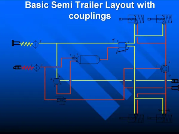
Feasibility study - tunnel space Fits above the LHC ring at a 1.35 m beam-to-beam vertical distance (some cabling exceptions in straight sections) Basic Layout of LER G. de Rijk
Feasibility study - tunnel space Basic Layout of LER G. de Rijk
Feasibility study - tunnel space Basic Layout of LER G. de Rijk
Layout (1) • Arc cells match the LHC cell length • 4 Combined function magnets (12 m) per half cell Bmax 1.595 T, G = ± 4.969 T/m • Dispersion suppressor with combined function magnets (8 m). • Short straight sections with corrector magnets are similar to those for VLHC • Straight sections have 4 m long quads • Low beta insertion is common with the LHC talk by J. Johnstone FNAL Basic Layout of LER G. de Rijk
The challenge: Experiment bypasses There are: 2 large (ATLAS & CMS) 2 less big (ALICE & LHCb) experiments to bypass For this study we assume that after an upgrade only ATLAS and CMS will remain Basic Layout of LER G. de Rijk
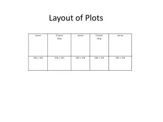
Experiment bypass options • Bypass the experiments in a tunnel • typically be at least 2 x 300 long • Digging a bypass requires to empty the main tunnel at the junctions • An extra shaft is probably needed for each bypass • At least a year shutdown • Very costly: >20 MCHF per tunnel • Remark: the optics could be very problematic • Bypass the experiments through the detectors • Drilling a hole through the detectors is probably a very bad idea • There is a hybrid option with (1) passing in between the muon chambers : to be studied later • Remark: the optics could be very problematic • Bypass the experiments through the LHC beampipe • Bump beam down (and back up) into beam experimental beam pipe • Study concentrates on this option Basic Layout of LER G. de Rijk
Injection / bypass scheme Use existing injection channel Fast switched transfer lines in IP1 and IP5 RF, dump and cleaning separate from LHC Basic Layout of LER G. de Rijk
Injection / bypass scheme (2) LER ops: D and FSD on LHC ops: D and FSD off • Beam train of 89 ms + gap of 3 ms • To inject in LHC switch Fast Switching Dipole off during 3 ms gap • The following FSD go off in sequence when the gap passes Basic Layout of LER G. de Rijk
Transfer between LER and LHC (1) • Horizontal separation 150 ==> 0 mm • Vertical separation 1350 ==> 0 mm • One set of fast switched dipoles only at the LHC side of a transfer line • horizonal bend 2 is made by tilting the vertical bends Talks: J. Johnstone and H. Piekarz Basic Layout of LER G. de Rijk
Transfer between LER and LHC (2) Talks: J. Johnstone and H. Piekarz Basic Layout of LER G. de Rijk
Timing sequence • Injection plateau of ~ 400 s • Ramp up time from 0.45 TeV to 1.5 TeV is 300 s. • Fast Pulsed Dipoles ramp down in 3 ms Basic Layout of LER G. de Rijk
Timing sequence • Neighbouring fast switching magnets switch off at different times • Timing sequencing and magnetic decoupling of FSDs are important Basic Layout of LER G. de Rijk
Machine set-up option After an LHC dump: • If the low beta insertions can be ramped down fast • Then LER can setup while the LHC main magnets are still ramping down Basic Layout of LER G. de Rijk
Conclusing remarks • LER fits into the LHC arcs (with ease). • The main two-in-one superferric combined function magnets are of an existing technology • The bypass through the experimental beam pipe is possible. • Dipole magnets which can be switched off fast, are crucial. • LER is a dedicated injector for the LHC. • A future application is LER as DLHC injector Basic Layout of LER G. de Rijk