Download
1 / 57
610 likes | 865 Views
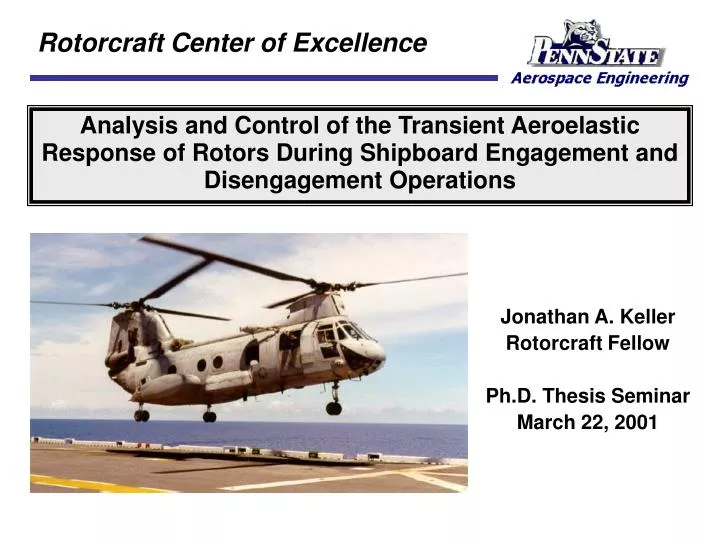
Rotorcraft Center of Excellence. Analysis and Control of the Transient Aeroelastic Response of Rotors During Shipboard Engagement and Disengagement Operations. Jonathan A. Keller Rotorcraft Fellow Ph.D. Thesis Seminar March 22, 2001. Presentation Outline. Introduction Previous Research

E N D
Rotorcraft Center of Excellence Analysis and Control of the Transient Aeroelastic Response of Rotors During Shipboard Engagement and Disengagement Operations Jonathan A. Keller Rotorcraft Fellow Ph.D. Thesis Seminar March 22, 2001
Presentation Outline • Introduction • Previous Research • Objectives • Approach • Results • Conclusions
Introduction • Unique challenges in ship-based operation of helicopters • Small, moving deck area • Strong & unsteady winds (often up to 50 knots) • Unusual airflow patterns around ship decks • Engagement (startup) of rotor system not mundane Low RPM = Low CF High winds = Potentially high Aerodynamic Forces W (%NR) High blade flapping
Historical Motivation • Past problems for Sea King (RN) and Sea Knight (USN) • Blade-to-fuselage contact (114 for H-46!) - High blade loads • Forcesconservative limits to be placed on wind conditions conducive to safe engagement operations • Reduces operational flexibility of helicopter H-46 Sea Knight H-3 Sea King
Styrofoam Pegs Greasy Board Engage/Disengage Testing • Safe conditions were determined in at-sea tests • Tests for every ship/helicopter/landing spot combo, but: • Problems often occurred within “safe” envelopes • Engage/Disengage testing cancelled in 1990 • Analytic methods needed! Took 5 days, 15 people, $150k No control of winds or seas Calm weather = wasted tests
Present Day Motivation • H-46 tunnel strikes still frequently occur • At least 3 last year aboard LHD type ships • Use of Army helos on Navy ships (JSHIP Program) • Army helos not designed for naval ops - no rotor brake? • Apache elastomeric damper loads during startup • Broken flap stop for Blackhawk during engagement op • Chinook is much like Sea Knight H-47 Chinook H-46 Sea Knight
Future Motivation • USMC and USN (hopefully) purchasing V-22 • V-22 blades much shorter than articulated blades • Excessive rotor gimbal tilt angles may be a possibility • Contact with between blades & wing/fuselage not a concern • Contact between gimbal and restraint potentially high loads Rubber Spring Gimbal Restraint
Presentation Outline • Introduction • Previous Research • Objectives • Approach • Results • Conclusions
Early Engage/Disengage Research • Willmer, Burton, & King at Westland (1960s) • Investigated Whirlwind, Wasp, and Sea King helicopters • Leone at Boeing Vertol (1964) • Investigated H-46 Sea Knight tunnel strikes • Measured and predicted loads during blade-droop stop impacts • Healey et al at Naval Postgraduate School (1985-1992) • Measured model-scale ship airwake for LHA, DD, AOR • Unsuccessfully investigated H-46 Sea Knight tunnel strikes • Kunz at McDonnell Douglas (1997) • Investigated high loads in AH-64 Apache elastomeric dampers
Recent Engage/Disengage Research • Newmanat University of Southampton (1985-1995) • Developed elastic F-T code for single rotor blade • Articulated or hingeless hubs • Articulated rotors more prone to blade sailing than hingeless • Correlated code w/ model-scale rigid R/C helicopter tests • Geyer, Keller, Kang and Smith at PSU (1995 - Present) • Developed F-L-T code for multiple rotor blades • Articulated, hingeless, teetering, or gimballed hubs • Simulated H-46 Sea Knight engagements and disengagements • Botasso and Bauchau (2000) • Multi-body modeling of engagement and disengagement ops
Presentation Outline • Introduction • Previous Research • Objectives • Approach • Results • Conclusions
Control rotor response to expand engage/disengage envelopes Objectives • Develop unique “in-house” analysis code to: • Increase physical understanding of engage/disengage behavior • Accurately predict safe rotor engage/disengage envelopes wtip (%R) Safe Region Unsafe Region
Technical Barriers • Limited data of engage/disengage ops or ship airwake • Simulation of a complex transient aeroelastic event • Rotor speed is a function of time W 0 andW(t) • Flap/lag stop or gimbal restraint impacts at low W • Complicated ship airwake and aero environment high a, L, m Ship Airwake H-46 Data H-46 Data W (%NR)
Presentation Outline • Introduction • Previous Research • Objectives • Approach • Results • Conclusions
Vz Vx Vy VWOD yWOD Ship Airwake Modeling • Specify speed (VWOD) & direction (yWOD) relative to ship center • Determines ship airwake (Vx, Vy, and Vz) in plane of rotor • Vx, Vy in plane velocities, Vz vertical velocity
Simple Ship Airwakes • Simple airwake types derived from tests (Ref. Newman) • Vz = vertical velocity, k = “gust” factor Vx = VWOD cos yWOD Vy = -VWOD sin yWOD Horizontal Airwake Vz = 0 VWOD Vz Constant Airwake Vz = kVWOD VWOD Vz max Linear Airwake Vz = kVWOD VWOD max
CFD Generated Ship Airwakes USN FFG SFS Flight Deck
yWOD = 270° yWOD = 0° Flow Acceleration Zone VWOD VWOD Recirculation Zone 70 kts 50 kts 60 kts 50 kts SFS Ship Airwakes • Along-wind airwake velocities 20 kts 50 kts 40 kts 40 kts
2-D Aerodynamic Modeling • Aerodynamics modeled with • Nonlinear quasi-steady aerodynamics (Ref. Prouty & Critzos) • Aero forces dependent upon instantaneous values of a, a, a • Nonlinear time-domain unsteady aerodynamics (Ref. Leishman) • Aero forces dependent upon time history of a, a, a • Model only validated for small a and L (< 25°) and M > 0.3 • Must switch to quasi-steady at high a and L (> 25°) and M < 0.1
va v’a wa w’a a vb v’b wb w’b b m Structural Modeling - Element • FEM used to accommodate different hub geometries • Articulated, hingeless, teetering and gimballed • 11 degrees of freedom per element • 4 flap, 4 lag, & 3 twist • Distributed blade loads • Inertial, Aerodynamic, Weight and Centrifugal Force • Inertial loads include rotor acceleration W CF Aero • • • > > > > > > > Weight
Structural Modeling - Blade • Articulated blade modeling • Require mechanisms to restrain flap (bhinge) & lag (zhinge) motion • Stops simulated with conditional springs Kb and Kz • Flap stops extend/retract at a specified rotor speed (t) Pitch Bearing Finite Element Conditional Lag stop springs Kz Flap Hinge Conditional Flap stop springs K Lag Hinge Control Stiffness Spring K Rotor Shaft
Structural Modeling - Rotor • Articulated or hingeless rotors • Teetering or gimballed rotors Blade motions are uncoupled b1, b2 and b3 independent b2 b3 M1 0 0 b1 [Mrotor] = 0 M2 0 0 0 M3 Blade motions are kinematically coupled b1 = -b2 b1 b2 M1 0 [Mrotor] = M2 0
Presentation Outline • Introduction • Previous Research • Objectives • Approach • Results • Baseline rotor • Passive control of H-46 rotor • Feedback control of gimballed rotor • Conclusions
Measured H-46 Baseline Baseline Rotor System • Representative of a “medium-sized” naval helicopter • Nb = 4 Articulated Blades • R = 25 ft • W0R = 750 ft/s • g = 7.35 • s = 0.076 • nb = 1.02/rev • nz = 0.30/rev • nq = 4.54/rev • bFS = ±1º • zLS = ±10º
Typical Engagement • Linear airwake • VWOD = 60 knots • k = 25% • Largest wtip occur W < 25%NR • Blade strikes flap stops repeatedly • Majority of wtip is elastic bending • rigid body wtip ±2%R • Large a in low W even near blade tip
Typical Engagement • Linear airwake • VWOD = 60 knots • k = 25% • Majority of vtip is rigid body motion • Blade strikes lag stop repeatedly • Largest torque due to impacts
Upward wtip Upward wtip Downward wtip Downward wtip Typical Wind Envelope • Engagement wind envelope • Shows largest downward and upward wtip with VWOD and yWOD VWOD = 60 kts yWOD = 30°
SFS Ship Airwake • What effect does a “realistic” ship airwake have on rotor deflections? SFS Flight Deck
Large upflow component over flight deck and over hangar face Little upflow over stern and flow decelerates near hangar face Large upflow component on windward side of flight deck Recirculation zone pushed away from flight deck Recirculation and downflow behind hangar face Spot #1 Engagement Envelope • Bow and port winds have largest wtip • Stern and 330° winds have small wtip Spot #1 (Closest to hangar)
Effect of Deck Position • Spots closer to hangar have larger wtip • Largest wtip consistently in port winds • wtip for Spot #1 are ~2wtip for Spot #3 Spot #1 Spot #2 Spot #3 Spot #1 Spot #2 Spot #3
Presentation Outline • Introduction • Previous Research • Objectives • Approach • Results • Baseline rotor • Passive control of H-46 rotor • Flap Damping • Spoilers • Feedback control of gimballed rotor • Conclusions
Control rotor response to expand engage/disengage envelopes Objectives • Develop unique “in-house” analysis code to: • Increase physical understanding of engage/disengage behavior • Accurately predict safe rotor engage/disengage envelopes wtip (%R) Safe Region Unsafe Region
Flap Damping on HUP-2 • Hydraulic flap dampers were used on 1950’s era HUP-2 • Dampers only active at low W • Above preset W dampers became inactive • Use same technique on H-46 Sea Knight • Not necessarily traditional hydraulic damper - MR or ER? • Use of mast causes drag penalty in forward flight Spring Mast Counterweight Damper Hub Blade
H-46 flap stops set at ±1º Flap damper has stroke of only 2° Majority of wtip is elastic bFS Cb Flap damper has no effect with a small stroke! Flap Damper Sizing for H-46 • Examine “worst-case” scenario - Spot #1 Airwake
Flap Damper Sizing for H-46 • Raise flap stop setting • Allows damper larger stroke • Keep droop stop setting at -1º No additional downward wtip Raise flap stop setting Flap damper has larger stroke Cb bFS Flap damper has much large effect!
SFS Spot #1 Envelope • Flap damper = 4Cz • Flap stop = 6° • Max wtip increased in 210°- 240° winds +30%R to +34.8%R • Min wtip decreased in 240°- 300° winds -22.4%R to -14.8%R • Min wtip not affected in bow winds Still -25.2%R Standard H-46 With Damper Max wtip Min wtip
Flap Damping in Bow Winds • Blade does not lift off bDS until t = 5 sec • Flap damper never has a chance to dissipate energy • Summary: • Min wtip decreased in most cases • bFS must be raised • Max wtip increased
Presentation Outline • Introduction • Previous Research • Objectives • Approach • Results • Baseline rotor • Passive control of H-46 rotor • Flap Damping • Spoilers • Feedback control of gimballed rotor • Conclusions
Objectives • Examine reducing flapping by reducing excessive lift • Leading-edge spoilers known to significantly reduce lift L Leading-edge spoiler L V V Without spoiler With spoiler (Ref. Brasseur)
Percentage of radius covered by spoilers? • Will rotor torque increase due to spoiler drag? Objectives • Spoilers are used only along partial-span • Gated spoilers are used on blade upper and lower surfaces • Spoilers only extended at low W < 25%NR and retracted into blade section at high W > 25%NR
Spoiler Coverage • H-46 engagement with varying amounts of spoiler coverage • Spoilers on outer 15%R (~3½ ft) are enough to reduce wtip H-46 Engagement SFS Spot #1 Airwake VWOD = 40 kts yWOD = 240°
Example Engagement SFS Spot #1 Airwake (Worst Case Scenario) VWOD = 40 kts yWOD = 240° Conclusions: Min and Max wtip reduced Max torque not affected
SFS Spot #1 Airwake Envelopes • Max wtip decreased in 210°- 270° winds +30%R to +23%R • Min wtip decreased in 240°- 300° winds -25.2%R to -17.5%R • Min wtip decreased in bow winds -23%R to -18.5%R • Conclusion: • Both Min and Max wtip reduced Standard H-46 With Spoilers Max wtip Min wtip
Presentation Outline • Introduction • Previous Research • Objectives • Approach • Results • Baseline rotor • Passive control of H-46 rotor • Flap Damping • Spoilers • Feedback control of gimballed rotor • Conclusions
Motivation • V-22 blades much shorter & stiffer than articulated blades • Rotor motion due to rigid body motion, not elastic bending • V-22 utilizes active “flap limiter” to reduce flapping in FF • Feedback from gimbal motion to swashplate inputs • Could flap limiter be used in engagement ops? Rubber Spring Gimbal Restraint
Structural & Aerodynamic Modeling • Rigid blade structural model • 2 degrees of freedom - gimbal pitch (b1c) and roll (b1s) • Linear quasi-steady aerodynamic model • Lift >> Drag b1C z y W x b1S Kb • Control System Settings Swashplate inputs
Optimal Control Theory • Cast equations of motion into state space form Disturbance d(t) due to: Airloads induced by ship airwake effects • Equations are Linear Time Variant (LTV) • W(t) and aerodynamic terms make pole placement ineffective • Use LQR theory and define performance index J • S(tf) = Final State Weight Q = State Weight R = Control Weight • Use Matrix Ricatti Equations to find gain matrix K Additional gain due to disturbance d(t)
Control System Limits • Swashplate actuators typically have limits in magnitude and rate • Time integration with control system limits Enforce control limits
Response in Constant Airwake • Simulated V-22 engagement • Vwod = 30 kts in Bow winds • Uncontrolled case: • q75 = q1c = q1s = 0 • Constant airwake distribution • k = 25% Vwod Conclusion: bmax reduced by 50% Min q75 limit reached
Optimal Control Assumptions • Gain K and disturbance effect v are functions of the ship airwake • Knowledge of the ship airwake is difficult to predict/measure • Ship anemometer reads relative wind speed and direction • Correlates to in-plane velocities Vx and Vy over flight deck Anemometer Vx and Vy may vary over the flight deck Vz is unmeasured! Vz Vx Vy VWOD yWOD