Download
1 / 33
350 likes | 671 Views
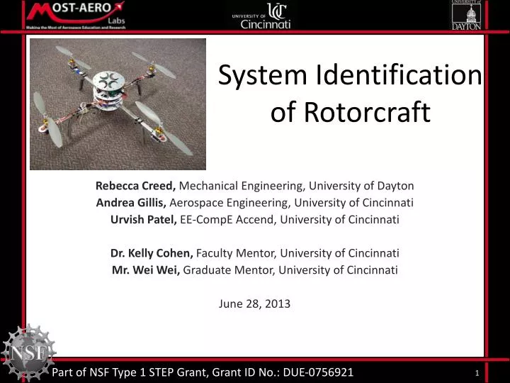
System Identification of Rotorcraft. Rebecca Creed, Mechanical Engineering, University of Dayton Andrea Gillis, Aerospace Engineering, University of Cincinnati Urvish Patel, EE-CompE Accend, University of Cincinnati Dr. Kelly Cohen, Faculty Mentor, University of Cincinnati

E N D
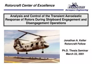
System Identification of Rotorcraft Rebecca Creed, Mechanical Engineering, University of Dayton Andrea Gillis, Aerospace Engineering, University of Cincinnati Urvish Patel, EE-CompE Accend, University of Cincinnati Dr. Kelly Cohen, Faculty Mentor, University of Cincinnati Mr. Wei Wei, Graduate Mentor, University of Cincinnati June 28, 2013 Part of NSF Type 1 STEP Grant, Grant ID No.: DUE-0756921
Introduction • Natural disasters take thousands of lives every year. • Many first responders perform dangerous rescue missions to save lives. • Technology will allow first responders to assess the situation more quickly and efficiently.
2012 Colorado Wildfire • The progression of the fire could not be anticipated. • Once the fire had become an issue, the best way to access it was unknown. • An autopilot equipped rotorcraft would be able to use a camera and assess the situation. Image courtesy of csmonitor.com
Why Autopilot? • Easy to use with simple controls • Increase the range of the rotorcraft • Without autopilot, the rotorcraft must remain in the operator’s line of sight • A dynamic model is necessary to develop an autopilot
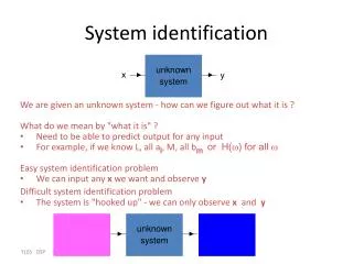
System Identification • A dynamic model is a representation of the behavior of a system (for this case, rotorcraft) • Two options for creating a dynamic model • System Identification • Wind Tunnel Testing
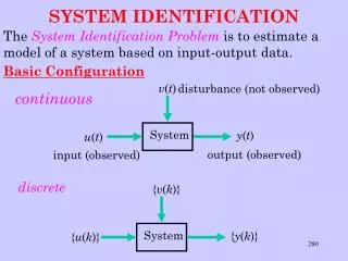
So, what is System Identification? System Inputs Outputs Given the inputs to a system, a system model can predict the outputs
Simple Example: Pushing a Sled Sled • Push(force) • Acceleration • Velocity • Displacement Input is the “pushing” force applied to the sled Output is the sled’s movement
System Inputs and Outputs • 4 inputs • Yaw • Pitch • Roll • Thrust • 9 outputs • 3 attitudes • 3 angular rates • 3 accelerations Aeroquad System
System Identification Flowchart Flight Testing Data Processing MATLAB Data Evaluation CIFER System Model Validation System Identified!
Flight Test • Inputs given to the rotorcraft by controller • Outputs recorded by the sensor stick (IMU)
How the quad-rotor works Roll Control move right/left • Yaw Control • spin cw/counter-cw • Pitch Control • move forward/backward
Data Processing Flight Testing • Record raw data in MATLAB program Data Processing Data Evaluation • Filter recorded data System Model • Reformat data for use in CIFER Validation System Identified!
Filter Data Sensor stick used in Rotorcraft – 9DOF Accelerometer ADXL345 Noisy Data Next Step Filtered Data Filter Picture from: www.sparkfun.com
Kalman Filter • Kalman filter finds the optimum averaging factor for each consequent state and also remembers some information about previous state
Kalman Filter for Linear System • x = filtered value • p = estimated error • q = processed noise • r = Sensor Noise • k = Kalman gain • p = p + q • k = p / (p + r) • x = x + k * (measured – x) • p = (1 – k) * p Kalman Predictor Equation Measurement Update Equation
Moving average • Similar results as Kalman filter for our system • Moving average is less efficient than Kalman filter
Moving average and Kalman Regular Kalman Moving Average
Data Evaluation – CIFER CIFER • stands for Comprehensive Identification from Frequency Responses • Advanced tool used for System Identification • Developed by the U.S. Army and the University of California Santa Cruz • We use CIFER to identify the Aeroquad system CIFER image from: http://uarc.ucsc.edu/flight-control/cifer/
Data Evaluation – FRESPID • First Step: • Finds the frequency response of our data • Uses windowing to combine FRESPID results • Finds a transfer function from our combined frequency response
Data Evaluation – FRESPID • Frequency response relates the inputs and outputs of our data Frequency Response Input Data Output Data
Data Evaluation – COMPOSITE • Second Step: • Finds the frequency response of our data • Uses windowing to combine FRESPID results • Finds a transfer function from our combined frequency response
Data Evaluation – COMPOSITE • COMPOSITE combines parts of the frequency responses that have the best coherence FRESPID Frequency Response COMPOSITE Frequency Response
Data Evaluation – NAVFIT • Last Step: • Finds the frequency response of our data • Uses windowing to combine FRESPID results • Finds a transfer function from our combined frequency response
Data Evaluation – NAVFIT Transfer Function Phase and Magnitude • NAVFIT fits a transfer function to the COMPOSITE frequency response COMPOSITE Frequency Response
Data Evaluation – Stability • CIFER produces transfer functions for three motions • These transfer functions model the Aeroquad system and must be stable Transfer Function = Poles should be on this side! Stable Example Unstable Example Negative real roots Positive real roots
UAV Advantages • Maneuverability • Capable of indoor flight • Safer for Crews • Endurance • Cost • Sushi Delivery Image courtesy of http://www.todaysiphone.com/2013/06/yo-sushi-delivering-food-on-ipad-controlled-trays/
Progress *Plan to submit Journal paper and Conference paper from this research
References • Bestaoui, Y., and Slim, R. (2007). “Maneuvers for a Quad-Rotor Autonomous Helicopter,” AIAA Infotech@Aerospace Conference, held at Rohnert Park, California, May 7-10, pp.1-18 • Chen, M., and Huzmezan, M. (2003). “A Combined MBPC/2 DOF H∞ Controller for a Quad Rotor UAV,” AIAA Guidance, Navigation, and Control Conference and Exhibit, held at Austin, Texas, August 11-14, n.p. • Esme, B. (2009). “Kalman Filter For Dummies.” Biligin’s Blog, <http://bilgin.esme.org/BitsBytes/KalmanFilterforDummies.aspx> (Mar. 2009). • Guo, W., and Horn, J. (2006). “Modeling and Simulation For the Development of a Quad-Rotor UAV Capable of Indoor Flight ,” AIAA Modeling and Simulation Technologies Conference, held at Keystone, Colorado, August 21-24, pp.1-11 • Halaas, D., Bieniawski, S., Pigg, P., and Vian, J. (2009). “Control and Management of an Indoor Health Enabled, Heterogenous Fleet,” AIAA Infotech@Aerospace Conference, held at Seattle, Washington, April 6-9, pp.1-19
References • Koehl, A., Rafaralahy, H., Martinez, B., and Boutayeb, M. (2010). “Modeling and Identification of a Launched Micro Air Vehicle: Design and Experimental Results,” AIAA Modeling and Simulation Technologies Conference, held at Toronto, Ontario Canada, August 2-5, pp.1-18 • Mehra, R., Prasanth, R., Bennett, R., Neckels, D., and Wasikowski, M. (2001). “Model Predictive Control Design for XV-15 Tilt Rotor Flight Control,” AIAA Guidance, Navigation, and Control Conference and Exhibit, held at Montreal, Canada, August 6-9, pp. 1-11. • Milhim, A., and Zhang, Y. (2010). “Quad-Rotor UAV: High-Fidelity Modeling and Nonlinear PID Control,” AIAA Modeling and Simulation Technologies Conference, held at Toronto, Ontario, Canada, August 2-5, pp. 1-10. • Salih, A., Moghavvemi, M., Mohamed, H., and Gaeid, K. (2010). “Flight PID controller design for a UAV quadrotor,” Scientific Research and Essays, ????, Vol. 5, No. 23, pp. 3660-3667. • Tischler, M.B., and Cauffman, M.G. (2013). “Frequency-Response Method for Rotorcraft System Identification: Flight Applications to BO-105 Coupled Fuselage/Rotor Dynamics,” University Affiliated Research Center: A Partnership Between UCSC and NASA Ames Research Center, pp. 1-13.