Download
1 / 1
10 likes | 145 Views
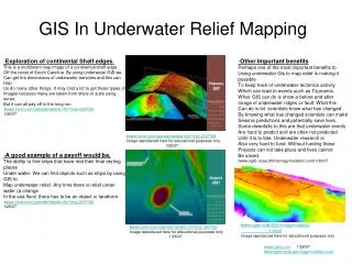
500. 400. Parallax Occlusion Linear. Parallax Occlusion linear restart. 300. Parallax Occlusion Binary. FPS. Parallax Linear & binary. 200. Relief Mapping Curvature. Real Displacement Mapping. 100. 0. 0.03. 0.035. 0.04. 0.045. 0.05. 0.055. 0.06. Distance.

E N D
500 400 Parallax Occlusion Linear Parallax Occlusion linear restart 300 Parallax Occlusion Binary FPS Parallax Linear & binary 200 Relief Mapping Curvature Real Displacement Mapping 100 0 0.03 0.035 0.04 0.045 0.05 0.055 0.06 Distance Silhouettes are easily handled without artifacts Displacement Mapping using Geometry Shaders Daniel Povlsendaniel.povlsen@gmail.com High Detail Mesh Reconstruction Highly detailed meshes look great – but they come at a cost. They take up space, they are expensive to animate and they do not lend themselves easily to high quality level of detail rendering techniques[4]. Hoppe et al. [2] provide an elegant solution to this problem, but being based on Loop subdivision [1], the technique is not (yet) applicable to GPU rendering. Introduction With the introduction of Shader Model 4.0, even more flexibility has been provided when programming the GPU. Our project has set out to investigate where the new methods for adding surface detail differs from the current. More specifically we will compare relief mapping using Shader Model 3.0 to displacement mapping using geometry shaders. This project has been done in collaboration with the group of Peder Johansen and Anders Scheel Nielsen. Technologies Used Geometry Shaders Geometry shading has been added as a major feature of Shader Model 4.0. They do not literally shade anything, but they do allow manipulation of the geometry in the graphics pipeline. The geometry shader takes as input single primitives and is able to output 0 to N primitives. Although N is limited ( implementation specific), this is ideal for tessellation. We use simple tessellation, where each triangle is potentially turned into 4 triangles, with newly created vertices on the midpoints of the original triangle edges. Transform Feedback With the addition of the transform feedback functionality it is possible to write geometry back into a vertex buffer after the geometry shader stage, without rasterization. Features Implemented Using the technologies described above, we have implemented a number of features. Streaming Tessellation The above two features working together means that we can tessellate our triangle mesh using a streaming method. We need 3 buffers to do this; 1 for the initial mesh and 2 temporary buffers to hold the result of the tessellation. First we stream our initial mesh through the tessellating kernel (geometry shader) to the first temp buffer. Then, as with double buffering, we stream from one temp buffer to the other, and then swap them, until we have reached the desired tessellation level (or no additional triangles have been created since the previous iteration). Finally we draw the geometry using ordinary normal mapping to add the last, fine detail to the lighting. Displacement Mapping Simple tessellation, in contrast to subdivision surfaces [1], does not add any surface detail in itself. We have implemented displacement mapping to add such detail to the tessellated mesh. Triangle vertices are simply displaced along the direction of the vertex normal accordingly to the height in the height map. Continuous Level of Detail Very small triangles usually do not add to the visual quality of the image. We have implemented a CLoD method based on screen space triangle sizes. Triangles with edges of length beneath a threshold, we do not tessellate further. We have also added a simple test to avoid tessellating triangles directly facing the viewer. High Detail Mesh Reconstruction Inspired by Hoppe et al. [2] we use the above techniques to reconstruct a high poly model from a low poly version. See middle column for further explanation. Frustum Culling We avoid subdividing triangles outside the view frustum, by culling each triangle against the view frustum in the geometry shader. Since we are potentially displacing a triangle from outside the frustum to the inside, we need to test the bounding box of the extruded volume of the displaced triangle. In collaboration with the other group we have performance tested the different methods using the cube shown at the bottom of the middle coloumn. The graph on the right speaks for itself. Displacement mapping is not a cheap technique for adding fine surface details. Results / Compared to Relief Mapping It does not scale linearly with screen coverage as does the other techniques. However, for larger displacements, it is superior to the quality and performance of the other methods. ProsCons + Easily handles silhouettes - Requires Shader Model 4.0 + Good for large scale displacements - Uses memory for streaming buffers + Geometry based, no stepping / Z artifacts - Needs high tessellation for fine details Conclusions and Future Work We have successfully implemented triangle mesh tessellation and displacement mapping entirely on a next generation GPU. Furthermore we have managed to reconstruct high detail meshes from a simple control mesh and height map. We believe that the advantages in using real geometry for adding (coarse) surface detail and for reconstructing high detail meshes will, in time, outweigh the added cost. However, for finer surface details, simple normal, parallax, and relief mapping will most likely remain superior. The geometry shader allows accessing information on adjacent primitives and as such does make way for better subdivision schemes. This would be interesting to investigate using a better subdivision method as in [3] and building a tool for creating the control mesh and displacement map for this method, as was done in [2] for Loop subdivision surfaces. Further enhancements could include detecting triangles covering areas of non-changing values in the normal map and avoid tessellating these triangles further. References and Acknowledgements [1] Loop, Charles Smooth Subdivision Surfaces Based on Triangles, 1987 [2] Hoppe, Hugues et al. Displaced subdivision surfaces, Proc. SIGGRAPH, 2000 [3] Vlachos, Alex et al. Curved PN Triangles, Proc. SI3D ,2001 [4] Akenine-Möller, Tomas et al. Real-Time Rendering 2nd Ed., p389-401, 2002 [5] NVIDIA OpenGL Extension Specifications for the GeForce 8 Series Architecture (G8x), 2007 Huge thanks to Peder Johansen and Anders Scheel Nielsen for giving invaluable feedback and for providing the models used in this project. Our idea is based on the same concept; from a detailed mesh, we use a tool to create a simplified control mesh and a normal / height map. During rendering we tessellate the control mesh to get a finer mesh and then displace it to reconstruct surface and silhouette details. By controlling the tessellation level we get continuous LoD almost for free and it is necessary only to animate the control mesh to get a fully animated reconstructed mesh. The 5 Stanford bunnies to the left, from the top, are; the control mesh, 3 levels of reconstructed high detail meshes and at the bottom the original bunny mesh. As can be seen in the middle image, the silhouette is already pretty good at only two levels of subdivision. Continuous Level of Detail Initially we based our level of detail selection on projected screen area of the triangles. However, not using the ability to look up information on neighboring triangles, we opted to make the decision based on triangle edges. If an edge of a triangle is longer than a threshold limit, we tessellate the triangle. The calculation for the adjacent triangle, sharing this edge, will be identical and both will be tessellated. Special care must be taken to avoid T-cracks, when an edge of a tessellated triangle is shared with a non-tessellated triangle. We handle this case by only morphing new vertices on longer edges to their final displacement, while vertices on shorter edges are kept on the edge. This works very well if no two adjacent triangles are more than a single subdivision level apart. When the input mesh has similar sized triangles, this is not a problem. Rendering Performance We have tested rendering performance of the Stanford bunny in 4 different levels of detail; starting with the control mesh. For comparison the original mesh is included as well. The test was done on a NVIDIA 8800GTX card in 1920x1200 resolution. LoDs and original mesh Displacement mapping needs high tessellation for finer details