Download
1 / 27
270 likes | 400 Views
WG3a Sources Summary. Jim Clarke on behalf of John Sheppard, Masao Kuriki, Philippe Piot and all the contributors to WG3a. Goals for WG3a. Review ILC electron and positron source requirements. Review proposed source designs. Make recommendation for the baseline reference design.

E N D
WG3a Sources Summary Jim Clarke on behalf of John Sheppard, Masao Kuriki, Philippe Piot and all the contributors to WG3a
Goals for WG3a • Review ILC electron and positron source requirements. • Review proposed source designs. • Make recommendation for the baseline reference design. • Develop list of R&D tasks. • Discuss design options. • Propose a timeline for the development of the ILC sources which includes criteria and milestones for technology selection. • Make a list of current activities; make a list of institutional interest in future development activities.
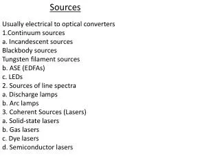
Electron source • 2 sessions dedicated to electrons • 7 presentations • Type of gun • DC or RF • What DC voltage to use • What RF scheme to use • Photocathodes • Lasers
OPCPA system for generation of trains of femtosecond pulses with ~800 nm wavelength I. Will, H. Redlin, MBI Berlin • OPCPA system generates trains of picosecond or femtosecond pulses t= 150 fs .. 20 ps (FWHM) • pulse energy: Emicro = 50…100 mJ Etrain = up to 80 mJ • Available wavelength: • l = 790…830 nm up to 900 us Easily stretched Far more energy than needed Output pulse train of the OPCPA K Floettmann, DESY
ILC polarized electron source, Baseline Recommendation! DC gun(s) laser room-temperature accelerating sect. standard ILC SCRF modules diagnostics section sub-harmonic bunchers + solenoids • DC gun: • 120 keV HV • Laser requirements: • pulse energy: ~ 2 mJ • pulse length: ~ 2 ns • # pulses/train: 2820 • Intensity jitter: < 5 % (rms) • pulse spacing: 337 ns • rep. rate: 5 Hz • wavelength: 750-850 nm • photocathodes: • GaAs/GaAsP • Room temperature linac: • Allows external focusing by solenoids • Same as e+ capture linac
Positron Source • 4 sessions dedicated to positrons • 13 presentations • 3 alternative schemes were considered in detail • Lively discussion on pros and cons of each scheme !!
Conventional Target Target material WRe 56kW absorbed Target rotates at 360m/s Operates at fatigue stress of material W Stein, LLNL
Positron Yield Positron yield is defined as the ratio of the number of captured positrons to that of incoming electrons striking the conversion target. Specification is 1.5 no safety margin W Gei, ANL
Primary e- source Beam Delivery System 5 – 100 GeV e- Bypass line Positron Linac IP 250 GeV 150 – 250 GeV e- Transfer Line Photon Collimators e+ DR Target e- Dump e- DR Helical Undulator Electron Linacs Photon Beam Dump 100 GeV 150 GeV Auxiliary e- Source Photon Target e+ pre-accelerator ~5GeV 2nd e- Source Adiabatic Matching Device Schematic Layout – Undulator @ 250GeV & Transfer Paths Undulator Based Source Many options for undulator placement etc D Scott, Daresbury
Undulator Prototypes 14mm SC, Rutherford Lab 10mm SC, Cornell 14mm PM, Daresbury D Scott, Daresbury
Target and Yield • Target • Material is Ti • 18kW absorbed • Rotates at 100 m/s • Factor of 2 safety margin in fatigue stress • The value of positron capture for undulator-based source is 3-4 larger than that of electron-based source because of better positron beam emittance after target. (Y Batygin, SLAC)
E-166 Experiment E-166 is a demonstration of undulator-based production of (polarized) positrons for linear colliders: - Photons are produced ~in the same energy range and polarization characteristics as for ILC; -The same target thickness and material are used as in the linear collider; -The polarization of the produced positrons is the same as in a linear collider. -The simulation tools are the same as those being used to design the polarized positron system for a linear collider. - Number of gammas per electron is lower ~210 times, however: (150/1)(2.54/10)(0.4/0.17)2. A Mikhailichenko, Cornell
E-166 at SLAC Undulator table Undulator table Positron table Positron table Vertical soft bend Vertical soft bend Gamma table Gamma table A Mikhailichenko, Cornell
E166 Undulator Area A Mikhailichenko, Cornell
E-166 Results • Number of photons agrees with expected • Gamma polarisation agrees with theory 82-99.3 %±10-20% • Number of positrons agrees with expected • Positron Polarisation = 95 %±30% • Simulated 84% A Mikhailichenko, Cornell
Compton Scheme laser pulse stacking cavities Compton ring positron stacking in main DR Electron storage ring to main linac T Omori, KEK
Proof of Principle at KEK T Omori, KEK
Summary of Experiment 1) The experiment was successful. High intensity short pulse polarized e+ beam was firstly produced. Pol. ~ 80% 2) We confirmedpropagation of the polarization from laser photons -> g-rays -> and pair created e+s & e-s. 3) We established polarimetry of short pulse & high intensity g-rays, positrons, and electrons. T Omori, KEK
Compton Scheme for ILC • Electron storage ring • Laser pulse stacking • Positron stacking ring • Two versions, based on either CO2 or YAG laser • Expect 60% polarisation
Schematic View of Whole System (CO2) ~2.5A average current
One laser feeds 30 cavities in daisy chain T Omori, KEK
i-th bunch on j-th DR turn -0.03 0.03 dEnergy/Energy e+ in a bucket Time -0.4 0.4 Longitudinal Pos. (m) e+ stacking in Damping Ring (simulation) 1st bnch on 1st trn 5th bnch on 5th trn 10th bnch on 10th trn T=0 ~110 msec before 11th bnch on 941st trn 11th bnch on 942nd trn 15th bnch on 946th trn ~10 msec before 21st bnch on 1882nd trn 20th bnch on 951st trn 100th bnch on 8479th trn ~10 msec + 110 msec ~20 msec ~100 msec + 110 msec stacking loss = 18% in total 100 bnchs on 9410th trn 100 bnchs on 18820th trn ~110 msec ~200 msec T Omori, KEK
Open Issues for Positron Sources • L-band warm structure 1ms operation : U , LC and Cv. • Target damage : Cv. • Radiation damage on target : U,LC • Thermal load of the capture section: Cv. • Damage by the operation failure : U (MPS) • Damage or failure by the instabilities : U • Degrade the electron beam quality: U • Positron Stacking in DR : LC • e beam stability in Compton Ring: LC • Vacuum pumping : U • Stability of integration of optical cavity :LC • Radiation loss, heat load in DR : LC • Fast Kicker operation with large kick angle for DR injection : U, LC and Cv (DR problem) • Mechanical failure on the rotation target: Cv and U Cv: Conventional U: Undulator LC: Laser Compton
Baseline • Baseline not yet agreed • A number of issues for each scheme will be examined in detail (next week) • Need some interaction with other groups (eg Damping Ring) • Generate Performance & Issues List • Aim to make recommendation for baseline (and alternative) next week