Download
1 / 23
230 likes | 403 Views
Building the Beta. CPU Design Tradeoffs. Maximum Performance : measured by the numbers of instructions executed per second. Minimum Cost : measured by the size of the circuit.

E N D
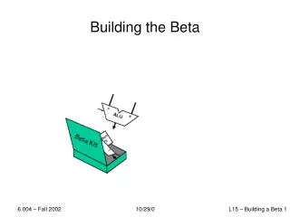
Building the Beta 10/29/0
CPU Design Tradeoffs Maximum Performance: measured by the numbers of instructions executed per second Minimum Cost: measured by the size of the circuit. Best Performance/Price: measured by the ratio of MIPS to size. In power-sensitive applications MIPS/Watt is important too. 10/29/0
Performance Measure Millions of Instructions per Second Clocks per instruction PUSHING PERFORMANCE ... TODAY: 1 cycle/inst. NEXT TIME: more MHz via pipelining NEXT NEXT TIME: fixing various pipelining issues 10/29/0
The Beta ISA Operate class: Reg[Rc] ← Reg[Ra] op Reg[Rb] Instruction classes distinguished by OPCODE: OP OPC MEM Transfer of Control Operate class: Reg[Rc] ← Reg[Ra] op SXT(C) Opcodes, both formats: ADD SUB MUL* DIV* *optional CMPEQ CMPLE CMPLT AND OR XOR SHL SHR SRA 10/29/0
Approach: Incremental Featurism Each instruction class can be implemented using a simple component repertoire. We’ll try implementing data paths for each class individually, and merge them (using MUXes, etc). Our Bag of Components: Steps: 1. Operate instructions 2. Load & Store Instructions 3. Jump & Branch instructions 4. Exceptions 5. Merge data paths Registers Muxes “Black box” ALU Memories 10/29/0
Multi-Port Register Files (independent Read addresses) 2 combinational READ ports*, 1 clocked WRITE port *internal logic ensures Reg[31] reads as 0 10/29/0
Register File Timing 2 combinational READ ports, 1 clocked WRITE port What if (say) WA=RA1??? RD1 reads “old” value of Reg[RA1] until next clock edge! 10/29/0
Starting point: ALU Ops 32-bit (4-byte) ADD instruction: Means, to BETA, Reg[R4] ← Reg[R2] + Reg[R3] First, we’ll need hardware to: • Read next 32-bit instruction • DECODE instruction: ADD, SUB, XOR, etc • READ operands (Ra, Rb) from Register File; • PERFORM indicated operation; • WRITE result back into Register File (Rc). 10/29/0
Instruction Fetch/Decode • Use a counter to FETCH the next instruction: PROGRAM COUNTER (PC) • use PC as memory address • add 4 to PC, load new value at end of cycle • fetch instruction from memory o use some instruction fields directly (register numbers, 16-bit constant) o use bits <31:26> to generate controls INSTRUCTION WORD FIELDS CONTROL SIGNALS 10/29/0
ALU Op Data Path OP: Reg[Rc] ← Reg[Ra] op Reg[Rb] 10/29/0
ALU Operations (w/constant) OPC: Reg[Rc] ← Reg[Ra] op SXT(C) 10/29/0
Load Instruction LD: Reg[Rc] ← Mem[Reg[Ra]+SXT(C)] 10/29/0
Store Instruction ST: Mem[Reg[Ra]+SXT(C)] ← Reg[Rc] 10/29/0
JMP Instruction JMP: Reg[Rc] ← PC+4; PC ← Reg[Ra] 10/29/0
BEQ/BNE Instructions BEQ: Reg[Rc] ← PC+4; if Reg[Ra]=0 then PC ← PC+4+4*SXT(C) BNE: Reg[Rc] ← PC+4; if Reg[Ra]≠0 then PC ← PC+4+4*SXT(C) 10/29/0
Load Relative Instruction LDR: Reg[Rc] ← Mem[PC + 4+ 4*SXT(C)] Hey, WAIT A MINUTE. What’s Load Relative good for anyway??? I thought • Code is “PURE”, i.e. READ-ONLY; and stored in a “PROGRAM” region of memory; • Data is READ-WRITE, and stored either • On the STACK (local); or • In some GLOBAL VARIABLE region; or • In a global storage HEAP. So why an instruction designed to load data that’s “near” the instruction??? Addresses & other large constants 10/29/0
LDR Instruction LDR: Reg[Rc] ← Mem[PC + 4 + 4*SXT(C)] 10/29/0
Exception Processing Plan: • Interrupt running program • Invoke exception handler (like a procedure call) • Return to continue execution. We’d like RECOVERABLE INTERRUPTS for • Synchronous events, generated by CPU or system FAULTS (eg, Illegal Instruction, divide-by-0, illegal mem address) TRAPS & system calls (eg, read-a-character) • Asynchronous events, generated by I/O (eg, key struck, packet received, disk transfer complete) KEY: TRANSPARENCY to interrupted program. • Most difficult for asynchronous interrupts 10/29/0
Implementation… How exceptions work: • Don’t execute current instruction • Instead fake a “forced” procedure call • save current PC (actually current PC + 4) • load PC with exception vector • 0x4 for synch. exception, 0x8 for asynch. exceptions Question: where to save current PC + 4? • Our approach: reserve a register (R30, aka XP) • Prohibit user programs from using XP. Why? IllOp: PUSH(XP) Fetch inst. at Mem[Reg[XP]–4] check for DIV opcode, get reg numbers perform operation in SW, fill result reg POP(XP) JMP(XP) Example: DIV unimplemented LD(R31,A,R0) LD(R31,B,R1) DIV(R0,R1,R2) ST(R2,C,R31) Forced by hardware 10/29/0
Exceptions Bad Opcode: Reg[XP] ← PC+4; PC ← “IllOp” Other: Reg[XP] ← PC+4; PC ←“Xadr” 10/29/0
Control Logic Implementation choices: • ROM indexed by opcode, external branch & trap logic • PLA • “random” logic (eg, standard cell gates) 10/29/0
Beta: Our “Final Answer” 10/29/0
Next Time: Pipelined Betas So let’s run down to the 6.004 lab and put Intel out of business! Hey, building a computer is not really all that difficult 10/29/0