Download
1 / 19
190 likes | 260 Views
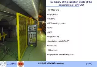
CNRAD news - Summary of the last TS and new PS EAIRRAD facility. Overall beam schedule for 2012 New installations and results RadMONs (2 nd and 3 rd Slots) Equipments to be tested in 2012 New PS East Area IRRAD. Overall Beam schedule for 2012.

E N D
CNRAD news - Summary of the last TS and new PS EAIRRAD facility • Overall beam schedule for 2012 • New installations and results • RadMONs (2nd and 3rd Slots) • Equipments to be tested in 2012 • New PS East Area IRRAD
Overall Beam schedule for 2012 • CNRAD experiment test area will run from March to December 2012 • 2013 → LS1 • Most probably, CNGS will not restart after 2013 • New schedule for LHC • New schedule for CNGS • The next technical stop will be on the week 38 (17/09 to 23/09) • A new schedule for the overall year will be available soon
New installations and results • RF MosFETs • Motivation • Having a deeper understanding of their behavior and limits • Used in the PS Booster over the last 20 years → 105 – 106 Gy without major failures • In the PSB → De-rated conditions: • VDS max = 125 V → Vdrain swings between 0-80V (40 VDC) • For the test: • Test setup is placed inside the target area • Dose expected from Slot3 to the end of the year ≈ 11 kGy (will depend on the new schedule) • Control/acquisition is located below station 2 with remote reset units • Test are performed in the worst case condition (80 VDC) • Evaluation: • Failure rate to single events • ID vs VG characteristic measurements vs dose
New installations and results • Cryo test • Motivation • Validate the design of a new power supply for the LHC beam screen heaters • Required dose: Up to 1 kGy → To validate up to the DS level • Decided test location : TSG45 – 451 • From Slot 3 to the end of the year ≈ 1 kGy (will depend on the new schedule) • For the application: • Power supply will be “off” during beam • Will be “on” only when the beam is off to supply the beam screen heaters • For the test: • Off-line measurements at the end of each slot → 3 boards with MosFETs, 1 board will be removed at the end of each slot to measure Ids vs Vgs curves. • On-line measurements • → Operate constantly or in switching mode to check if they failed during irradiation. Specific application.
New installations and results • TE/EPC – Puls AC/DC Power Supply • Motivation • Improvement of the Puls AC/DC power Supply used in the tunnel • Some of the components have been identified as potentially sensitive to radiation according to LHC failure observations. • Components have been replaced by new ones → New design • For the next slot, TE/EPC are scheduling to test 5 modified power supplies • As usual for TE/EPC, test location : TSG45 – 453 • During Slot 3 around 230 Gy, 1.5×10¹² HEH.cm-2
New installations and results • LED Warning System • Motivation • New prototype to be tested based on lessons learned from last year: • Safety lighting system powered by voltage transformer + Graetz bridge • Power LED technology • The system is tested on 2 different locations: • With monitoring : Position 453 • Without monitoring to test if the prototype can survive up to higher doses : Position 451 • Radiation levels since the beginning of the year: • Position 453: Dose: 180 Gy - ɸeq: 1.8×10¹²neq/cm2 – HEH : 1.3×1012 cm-2 • Position 451: Dose: 406 Gy - ɸeq: 4×10¹²neq/cm2 – HEH : 2.8×1012 cm-2 • Up to know we are covering locations up to DS levels (close the quadrupole magnets): • (Up to 10 years of nominal LHC operation for ɸeq and ɸHEH and 2 years in terms of Dose) • Will the system be installed in very harsh environments such as collimation, injection, dump extraction and inner triplet areas ?
New installations and results • BPM components • Motivation: Installation of new components • 4 SFP bidirectional transceivers: • 2 × manufacturers (Huihong – Ligent) • 1 SFP Transceiver (2 fibers) • FFTX Technology • QPS • Motivation • Up to know, only 1 µFIP failure with auto-reset has been detected and no failure on the PhotoMos relay has been observed so far. • Radiation levels: Dose = 66 Gy, 4×1011 = HEH/cm2and ɸeq = 5.8×1011 cm-2 • In terms of HEH fluence, we reached 4 years of LHC operation in the DS (close to quadrupole magnets) • QPS system has been relocated in a higher flux test area → Position 453 • Connection have been performed from Station 4 to TSG45 with a 40 meters cable (removal of the FIP diag on Station 4)
RadMONs – 2nd Slot RM8 box (5V) RM8 deported RadFETs: 100 nm 1000 nm RM10 box (5V) RM10 deported RadFETs: 100 nm 400 nm Difference between both RadFETs ≈ 34.5 % Difference between both RadFETs ≈ 40 % Previous Slot: Difference between 100 nm and 400 nm ≈ 35 % Previous Slot: Difference between 100 nm and 1000 nm ≈ 28 % At this location, a higher difference is observed with the 400 nm At this location, both 1000 nm and 400 nm responses are very similar Results should be taken with caution as the Co-60 calibration is missing for the 400 nm W8
RadMONs – 2nd Slot RM8 box (5V) RM8 deported RadFETs: 100 nm 1000 nm RM10 box (5V) RM10 deported RadFETs: 100 nm 400 nm At this location, both 1000 nm and 400 nm responses are very similar At this location, a higher difference with the 400 nm At position 455, the deposited dose is dominated by gamma and e- (Green) At position 463, protons are the dominant particles which deposit dose (Grey) The Co-60 for the 400 nm W8 is needed to understand
RadMONs – 3rd Slot RM10 deported (Target Area) RadFETs: 100 nm 400 nm RM7 box (5V) RM7 deported RadFETs: 400 nm 1000 nm RM10 box (3V) RM8 deported RadFETs: 100 nm 400 nm RM8 box (3V)
Equipments to be tested in 2012 • BPM components • LED warning system • QPS • Ethernet Switches • Wifi access points • Cryo power supply • TE/EPC components • New RadMON Maybe from Slot4 (17th September 2012)
New PS East Area IRRAD • Will be built in 2013 • What type of cables do you need ?
New PS East Area IRRAD • Preliminary list • Number of cables per station (probably 3/4 stations will be available) • Your feedback will be very useful (before the end of July – Perfect !)
Results of the Station2 position Dose/POT = 3.5×10⁻²⁰ ± 3.6 ×10⁻²¹ From calibration table: Dose/POT= 3.2×10⁻²⁰
Main results for position 455 Slot1&2 Comparison of the K factor for Slot 1 and 2: Slot1 Dose/POT = 1.3×10⁻¹⁸ ± 4 ×10-20 Diff(100nm/1000nm) ≈ 28 % Dose/POT = 1.8×10⁻¹⁸ ± 3.7 ×10⁻¹⁹ Slot2 Diff(100nm/400nm) ≈ 40 % Dose/POT = 2×10-18 ± 6.7 ×10⁻²⁰ Dose/POT = 1.2×10⁻¹⁸ ± 1 ×10-20
Main results for position 463 Slot1&2 Comparison of the K factor for Slot 1 and 2: Dose/POT = 3.04×10⁻¹⁸ ± 2.1 ×10⁻¹⁹ Slot1 Diff(100nm/400nm) ≈ 35.3 % Dose/POT = 4.7×10⁻¹⁸ ± 4.1 ×10⁻¹⁹ Slot2 Diff(100nm/1000nm) ≈ 34.6 % Dose/POT = 3.2×10⁻¹⁸ ± 1.7 ×10⁻²⁰ Dose/POT = 4.9×10⁻¹⁸ ± 7.2 ×10⁻¹⁹
RadMONs – 2nd Slot RM8 box (5V) RM8 deported RadFETs: 100 nm 1000 nm RM10 box (5V) RM10 deported RadFETs: 100 nm 400 nm At this location, both 1000 nm and 400 nm responses are very similar At this location, a higher difference with the 400 nm At position 463, protons are the dominant particles which deposit dose (green) At position 455, the deposited dose is dominated by gamma and e- (Black) Lower energy protons contribute more to the deposited energy at position 455. → ≈ 60 % of the dose deposited by protons is within 10 MeV < p+ < 25 MeV While at position 463 → ≈ 60 % of the dose deposited by protons is within 10 MeV < p+ < 40 MeV → ≈ 50 % p+ < 20 MeV → ≈ 50 %: 25 MeV < p+ < 60 MeV For both locations dose : → p+ < 125 MeV
RadMONs – 2nd Slot RM8 box (5V) RM8 deported RadFETs: 100 nm 1000 nm RM10 box (5V) RM10 deported RadFETs: 100 nm 400 nm At this location, both 1000 nm and 400 nm responses are very similar At this location, a higher difference with the 400 nm At position 463, protons are the dominant particles which deposit dose (green) At position 455, the deposited dose is dominated by gamma and e- (Black) Lower energy protons contribute more to the deposited energy at position 455. → ≈ 60 % of the dose deposited by photons is below E < 100 keV While at position 463 → ≈ 60 % of the dose deposited by photons is below E < 800 keV