Download
1 / 53
550 likes | 792 Views
Practical Many-Antenna Base Stations. Argos. Clayton W. Shepard Hang Yu, Narendra Anand , Li Erran Li, Thomas Marzetta , Richard Yang, Lin Zhong. Motivation. Spectrum is scarce Hardware is cheap. MU-MIMO Theory. More antennas = more capacity Multiplexing Power Orthogonality.

E N D
Practical Many-Antenna Base Stations Argos Clayton W. Shepard Hang Yu, NarendraAnand, Li Erran Li, Thomas Marzetta, Richard Yang, Lin Zhong
Motivation • Spectrum is scarce • Hardware is cheap
MU-MIMO Theory • More antennas = more capacity • Multiplexing • Power • Orthogonality
Data 2 Data 3 Data 1 Data 4 Data 5 Data 6
Why not? • Nothing scales with the number of antennas • CSI Acquisition • Computation • Data Transportation
Background: Beamforming Destructive Interference = Constructive Interference ? =
Background: Channel Estimation Due to environment and terminal mobility estimation has to occur quickly and periodically Measured channels are not reciprocal due to differences in the Tx and Rx hardware! Path Effects (Walls) The CSI is then calculated at the terminal and sent back to the BS For uplink, send a pilot from the terminal then calculate CSI at BS Align the phases at the receiver to ensure constructive interference Uplink? A pilot is sent from each BS antenna BS Tx Tx Tx Tx + Rx Rx Rx Rx = +
Background: Null Steering Null Null Null Null Null Data 1
Background: Null Steering Data 2 Null Null Null Null Null
Background: Multi-User Beamforming Data 2 Data 3 Data 1 Data 4 Data 5 Data 6
Background: Scaling Up Data 1
Background: Scaling Up Data 1
Background: Scaling Up Data 1
Background: Scaling Up Data 2 Data 3 Data 1 Data 4 Data 5 Data 6
Background: Linear Precoding • Calculate beamweights • Every antenna has a beamweight for each terminal • Multiply symbols by weight, then add together:
Recap • Acquire CSI • Calculate Weights • Apply Linear Precoding
Scalability Challenges • Acquire CSI • M+K pilots, then M•K feedback • Calculate Weights • O(M•K2), non-parallelizable, centralized data • Apply Linear Precoding • O(M•K), then O(M) data transport
Argos’ Solutions • Acquire CSI • New reciprocal calibration method • Calculate Weights • Novel distributed beamforming method • Apply Linear Precoding • Carefully designed scalable architecture O(M•K) → O(K) O(M•K2) → O(K)* O(M•K) → O(K) *
Solutions • Reciprocal Calibration • Distributed Beamforming • Scalable Architecture
Channel Reciprocity • Pilot transmission source? • Basestation • Terminal • Base station pilot transmission • Requires feedback • M pilots (M ≥ K) • Terminal pilot transmission • No feedback • K pilots
Channel Reciprocity TxA+RxC-TxC-RxA TxA+C+RxC-TxC-C-RxA Tx/Rx Chain differences require calibration Can we do this without terminal involvement? TxC TxA TxB RxC RxA RxB TxB+RxC-TxC-RxB Channel Estimation Transmission
Key Idea Any constant phase shift results in same beampattern! = =
Channel Reciprocity TxA+RxC-TxC-RxA TxA-RxA TxC TxA TxB RxC RxA RxB TxB-RxB TxB+RxC-TxC-RxB Channel Estimation Transmission
Internal Reciprocal Calibration • Find phase difference between A and B • Tx from A: • Phase offset = TxA-RxA • Tx from B: • (TxB-RxB) TxA+C+RxB TxB+C+RxA TxA+RxB- TxB-RxA TxA TxB RxA RxB • add phase difference • + (TxA+RxB- TxB-RxA) = TxA-RxA
Solutions • Reciprocal Calibration • Distributed Beamforming • Scalable Architecture
Problems with Existing Methods • Central data dependency • Transport latency causes capacity loss • Can not scale • Becomes exorbitantly expensive then infeasible
Conjugate Beamforming • Requires global power scaling by constant: • Where, e.g.: • This creates a central data dependency
Conjugate Beamforming Power Bad Channel BS Good Channel Okay Channel
Conjugate Beamforming Power Low Power BS High Power Normal Power
Distributed Conjugate Beamforming • Scale power at each antenna: • Maximizes utilization of every radio • More appropriate for real-world deployments • Quickly approaches optimal as K increases • Channels are independent and uncorrelated
Distributed Conjugate Beamforming High Power BS High Power High Power
Solutions • Reciprocal Calibration • Distributed Beamforming • Scalable Architecture
Architectural Design Goals ? • Scalable • Support thousands of BS antennas • Cost-effective • Cost scales linearly with # of antennas Data …
Linear Precoding … K … … K … K M … K
Scalable Linear Precoding … K … … K … K M … K
Scalable Linear Precoding Common Databus! … K … … K … K M … K
MUBF Linear Precoding: Uplink … K … … K … K M … K
Scalable Linear Precoding Constant Bandwidth! … K … … K … K M … K
Partition Ramifications • CSI and weights are computed and applied locally at each BS radio • No overhead for additional BS radios • No central data dependency • No latency from data transport • Constant data rate common bus (no switching!) • Unlimited scalability!
How do we design it? • Daisy-chain (series) • Unreliable • Large end to end latency • Token-ring | Interconnected • Not amenable to linear precoding • Variable Latency • Routing overhead … • Flat structure • Unscalable • Expensive, with large fixed cost … …
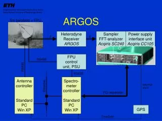
Solution: Argos Architecture Central Controller Data Backhaul … Argos Hub Argos Hub Argos Hub … Module Module Module Module Module … … Module Radio Radio Radio
Argos Implementation WARP Module WARP Module WARP Module Daughter Cards Daughter Cards Daughter Cards … … Power PC Power PC Power PC Central Controller (PC with MATLAB) Central Controller Radio 1 Radio 1 Radio 1 FPGA FPGA FPGA Ethernet Radio 2 Radio 2 Radio 2 FPGA Fabric FPGA Fabric FPGA Fabric Argos Hub Argos Hub Radio 3 Radio 3 Radio 3 Peripherals and Other I/O Peripherals and Other I/O Peripherals and Other I/O Hardware Model Hardware Model Hardware Model Ethernet Argos Interconnect Argos Interconnect Radio 4 Radio 4 Radio 4 Module Sync Pulse Module Clock Board Clock Board Clock Board … Clock Distribution … Module 16
Central Controller WARP Modules Argos Interconnects Sync Distribution Clock Distribution Argos Hub Ethernet Switch
Linear Gains as # BS Ant. Increases Capacity vs. M, with K = 15
Linear Gains as # of Users Increases Capacity vs. K, with M = 64
Scaling # of Users with 16 BS Ant. Capacity vs. K, with M = 16