Download
1 / 15
150 likes | 282 Views
LSST Photometric Calibration. D. Burke SLAC/KIPAC DOE SLAC Program Review June 6-7, 2006. The LSST Mission. Photometric survey of half the sky ( 20,000 square degrees). Multi-epoch data set with return to each point on the sky every 4-5 nights for up to 10 years.

E N D
LSST Photometric Calibration D. Burke SLAC/KIPAC DOE SLAC Program Review June 6-7, 2006
The LSST Mission • Photometric survey of half the sky ( 20,000 square degrees). • Multi-epoch data set with return to each point on the sky every 4-5 nights for up to 10 years. • Rapid cadence (new pointing every 40 seconds) with prompt transient alerts. • Deliverables • Archive 3 billion galaxies with photometric redshifts to z = 3. • Detect 250,000 Type 1a supernovae per year (with photo-z < 0.8).
Goals for Stellar Photometry Except as noted, specifications are given for isolated bright stars (17 < r < 20). • Repeatability of measured flux over epochs of 0.005 mag (rms). • Internal zero-point uniformity for all stars across the sky 0.010 mag (rms) in g,r,i ; < 0.020 in other bands. • Transformations between internal photometric bands known to 0.005 mag (rms) in g,r,i; < 0.010 to other bands. • (This is a specification on the absolute accuracy of measured colors.) • Transformation to a physical scale with accuracy of 0.020 mag.
LSST Celestial CalibrationFull Advantage of Cadence and Replication LSST Calibration Standards Start with existing catalogs – e.g. SDSS to r < 20. LSST single-visit depth (5) r = 24.5. LSST single-image saturation r 17. Use of photometric nights to build LSST standards catalogs. Hydrogen white dwarfs becoming the standard of choice. SDSS ~ 2000 confirmed equatorial WDs (18 < r < 20). Cross check with WDs (few dozen) observed with HST. LSST Calibration Sentinels Expect 100 main-sequence stars r < 20 every chip every image. Overlapped tiling of the sky in each epoch. Each point on the sky in repeated epochs.
Rapid-Paced Multi-Epoch SurveysSloan SDSS Precursor Southern Survey 300 deg2along celestial equator. Photometry for 870,000 stars observed in multiple epochs. Main sequence stellar color locus is quite narrow.Use this to evaluate and monitor instrumental and observational parameters. Projections of main sequence locus in gri and riz. Z. Ivezic, et al. (SDSS) Standards Workshop Blankenberge, 2006.
gri Sloan SDSS PrecursorSystematic Errors and Uniformity of Photometry Errors in photometric flat-fielding determined from averaging large numbers of stars across the sky within fixed detector boundaries. Uniformity of zero points: gri 5 milli-mags uz 10 milli-mags. Meets LSST goals.
Toward Absolute LSST Photometry An R&D program. Separate the problem into three parts: 1. Instrumental “flat field” and calibration. Stable and uniform reconstruction of photons in the telescope pupil. Absolute calibration of detector. 2. Measure atmospheric extinction and emission. • Photons at the top of the atmosphere. 3. Image processing, standardization, and verification. • Algorithms and celestial standards.
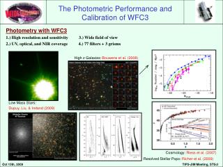
Dome Screen Tunable Laser Calibrated Photodiodes QE nm Instrumental Flat FieldingLSST andPanSTARRS Collaboration Wavelength dependence calibrated at NIST with relative accuracy of a part in a thousand or better. Product is a “flat-cube” of combined optical efficiency and electronic response at coordinates (i, j, ).
Back-Lit Diffuse Dome Screen Concept Sketch Side-Emitting Optical Fiber Mirror Diffuser Collimator Somta Corp of Riga, Latvia 800 m fused silica. 450-1100 nm bandpass. Y. Brown (Harvard)
FPA Optical Calibration • Calibrated photodiodes in FPA – absolute sensor response. • Monitor flux at focal plane during instrumental flat-fielding. • Scan standard stars across photodiodes and sensors.
PC Full Prototype Testing QE Fringe patterns Dark current CTE and cosmetics Crosstalk Full well Gain and RON Persistent image calibrated photodiode CfA controller sensor light-tight box integrating sphere filter shutter dewar dewar lamp x-y-z stage with pinhole projector temp. controller temp. controller lamp stage controller Camera ProductionIndividual Sensor Tests at BNL Production Sensors Vendor and BNL optical and electronic acceptance tests. Precise metrology done to specifications.
Camera ProductionOptical Calibration of Camera Subsystems Will do optical calibrations of assembled rafts and final camera. Optical flat-field of raft at BNL. Goal is ~1% relative calibration at (i, j, l). Optical flat-field of assembled camera at SLAC. Goal is ~ 0.5% relative calibration at (i, j, l). But subsystem calibrations at BNL and SLAC are not well defined in terms of SRD specifications since we can not create the LSST optical beam. Other issues: Uniformity of illumination - vignette and scattered light (any set-up). Thermal calibration and control. Cleanliness and repeatability of test set up (especially raft-level).
Integrated Camera Test and Calibration When … Camera is completed and sitting in SLAC assembly room. Electronics and DAQ working. Peripherals (shutter, filters, etc) in place and working. Goal Verify we are ready to ship the Camera to the mountain. Method Run the camera as if it were taking data on the telescope! Images to Record and Analyze Bias frames. Darks (long and short). Flats. Laser “stars”.
Assembled Camera Optical Calibration Challenge to obtain uniform illumination through all and/or part of refractive optics. Fiber driven screen? Integrating sphere? Laboratory Screen (TBD) – Illumination? – Shape? Camera Goal is “flat-field” at 0.5%, with transfer of calibration to camera on the telescope uncertain by perhaps a “smooth” function. Calibrated Photodiodes Tunable Laser
Laser “Star” Schematic Photodiode Array (or Telescope) Laser Source (2.6 cm aperture) Reference Photodiode 14 – 23.6 degrees L1 L2 Filter L3 FPA Not To Scale (Need ray-trace of the optics.) Reflectivity R ~ 0.3%. (Not all reflections shown.) 300 m (4cm away) 30 m (Approximate FWHM of LSST PSF at 0.6 arc-sec seeing.)