Download

1 / 27
270 likes | 400 Views
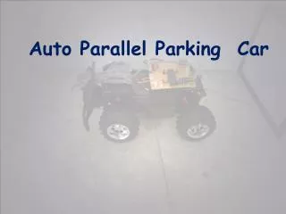
Autonomous Parallel Parking Alex Braun & Sergey Katsev. Overview. Objectives User Interface Algorithms Utilized Hardware Hardware Design Current Status. Objectives/Performance Specs. Follow a reflective track Receive user commands over a wireless interface Leave track and parallel park

E N D
Overview • Objectives • User Interface • Algorithms • Utilized Hardware • Hardware Design • Current Status
Objectives/Performance Specs • Follow a reflective track • Receive user commands over a wireless interface • Leave track and parallel park • Leave parking space and reacquire track • Minimum parking space 2 car lengths • Travel speed .5 – 1 foot per second • Capable of following any turns greater than vehicle turning radius
Implementation • Vehicle: • 1:12 Scale model of a Lincoln Navigator • Chassis and drive motor from original RC car • Steering implemented with Futaba S3003 Servo motor • Power • 9.6V rechargeable NiCad battery pack • Voltage regulators used to provide 5V power to electronics and isolate power planes
User Interface • Remote control used to issue user commands • Vehicle responds with actions and LED status lights • Remote uses 9V battery
User Interface • Status lights will indicate: • Current operating mode: • Manual • Automatic • Looking for track • Following track • Looking for Space • Parking • Parked • Error • Waiting for user parking override • “Turn Signal”
Sensor Layout • IR arrows show direction of beam • Wireless interface used for remote control user commands (more later)
Algorithms – Track Following • Front sensors used to determine when to turn • Two turning angles • Rear sensors used when acquiring the track and as a backup if all front sensors are lost
Algorithms – Parking • Minimum parking spot size 2 car lengths • Algorithm iterates if can not fit in spot in one motion
Utilized Hardware • Processing: • Onboard HCS12 • Sensors • Track Sensors • Fairchild QRE00034 Infrared Reflective Sensor • Used with a comparator to provided digital input to the HCS12
Utilized Hardware • Speed Sensor • Fairchild QRE00034 Infrared Reflective Sensor • Used with a comparator and a shaft encoder to produce a timer interrupt every quarter revolution of the rear wheels
Utilized Hardware • Collision Detection • Sharp GP2D120 Infrared Distance Sensors • Analog value fed to HCS12 through ADC • Parking Space Detection • Sharp GP2D150A Infrared Distance Sensor • Provides digital detection at ~15cm
Power Consumption Component Estimated Maximum Power Consumption DC Motor 2.7W Servo Motor 2W Curb and Vehicle Collision Sensors 0.30W x 4 = 1.2W Parking Space Sensor 0.30W Track Sensors .2W x 5 = 1W Vehicle Speed Sensor .2W Wireless Receiver 164mW HC-12 1W Misc ICs and LEDs ~ .2W x 10 = 2W TOTAL 10.6W
Hardware • Ribbon cable used to connect HC12 to PCBs • PCBs stacked to maximize available board space • Final product will (hopefully) fit inside original vehicle cover
Hardware – Drive Electronics • Motor draws 1.6A max. • Texas Instruments SN754410 Quad Half H-Bridge used. • 1A sustained load capacity, 2A peak load (per half H-bridge) • Two H-bridges used in parallel H-bridge functional schematic
Hardware – Wireless Interface • Ming 4-bit Tx/Rx • 300MHz AM • Uses Holtek Encoder and Decoder chips • Remote contains 74LS922 Key matrix decoder with debounce protection
Hardware – Sensor Input Conditioning • Two quad binary comparator circuits • Threshold set at 4.0V, established experimentally • Separate voltage regulator • Will contain HC12 inputs for all digital sensors
Costs Component Retail Price Actual Price Vehicle Assembly $50 $50 Track Sensors (5 total) $3.25 $0 Collision Detection (4 total) $48.80 $48.80 Parking Space Detection $13.23 $13.23 Wireless Kit $30.00 $30.00 Servomotor $9.80 $0 H-Bridge $1.35 $0 HCS12 $160 $0 Misc $70 $50 TOTAL $386.03 $192.03
Current Vehicle Status Receiver Rear track sensors Front Track Sensors DC Motor Steering Servo Comparators HCS12 H-Bridge
Difficulties • Speed Controller – “Pseudo” Shaft Encoder • Heat Dissipation – May have to place a second voltage regulator in parallel for drive electronics • HCS12 operates differently in DBUG12 mode than it does in LoadEE mode, so tracing code is practically impossible
Testing Methodology • Unit testing of both software and hardware units • Unit integration and system-wide testing • Extensive operation to ensure proper burn-in • For code: “Desk Checks” by the person who didn’t write the code
Questions? • Thank you!