Download
1 / 1
20 likes | 191 Views
Seismic networks Amadej Trnkoczy 1) , Jens Havskov, Lars Ottemöller 2) and Peter Bormann 3)

E N D
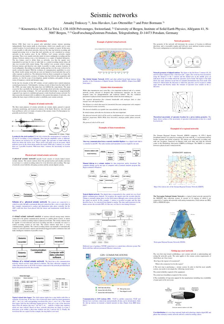
Seismic networks Amadej Trnkoczy 1), Jens Havskov, Lars Ottemöller 2) and Peter Bormann 3) 1) Kinemetrics SA, ZI Le Trési 2, CH-1028 Préverenges, Switzerland, 2) University of Bergen, Institute of Solid Earth Physics, Allégaten 41, N-5007 Bergen, 3) 3)GeoForschungsZentrum Potsdam, Telegrafenberg, D-14473 Potsdam, Germany Introduction Before 1960, there were in general only individual seismic stations operating independently. Each station made its observations, which were usually sent to some central location, if several stations were operating in a country or region. In that sense it was possible to talk about networks, however the time lag between recording and manual processing were so long that such networks are not considered as seismic networks in the modern sense. In the 1960'ties, 'real' seismic networks started operating. These were mainly networks made for micro-earthquake recording and the distance between stations were a few kilometers to a couple of hundred kilometers. The key feature, used to define them as networks, was that the signals were transmitted in real time by wire or radio link to a central recording station where all data was recorded with central timing. This enabled very accurate relative timing between stations and therefore also made it possible to make accurate locations of local earthquakes. Recording was initially analog and has over the years evolved to be nearly exclusively digital. With the evolution of communication capabilities to cover the whole world, seismic networks are now not limited to local networks but can be either regional or global too. The distinction between them is primarily no longer the differences in data transfer, accuracy of timing, time lag between data acquisition and analysis, etc, but the scope of investigation, spatial resolution, and quality of data in terms of frequency content and dynamic range. In the last two decades of the 20th century, several countries have started numerous seismological projects. Unfortunately, viewing several of them from the latter half of the 1990s, one must realize that many have not fulfilled the expectations. The main reason for this is probably the shortage of knowledge about networks, instrumentation and data processing techniques. Yet such specialized knowledge is unquestionably required if one expects to establish and operate a truly beneficial seismic network. For that reason this document will, in addition to the general description of networks, also outline the basic steps to follow in order to establish a new seismic network. Network geometry The geometry of the network will determine the accuracy of location in different directions, and a reasonably regular grid will give most uniform location accuracy. The worst configuration is a network with aligned stations. Example of global virtual network Network geometry of aligned stations. The figure to the left shows 3 stations (S1, S2 and S3) almost aligned in the x-direction (left - right). The event has been located by using the distances to the 3 stations and the shaded area in the middle gives an indication of the area within which the epicenter can be found. The figure to the right shows the same situation except that an azimuth determination has been made with station S1 which limits the direction to which the epicenter can be located to within angle shown and thereby makes the estimate of epicenter error smaller in the y-direction. The Global Seismic Network (GSN) and other global broadband stations being member of the Federation of Digital Seismic Networks (FDSN). (Figure from IRIS home page.) Seismic data transmission While data transmission may seem like a less important technical task of a seismic network, poorly selected or designed data transmission capacities are the most frequent cause for disappointments and technical failures. Thekey technical parameters in physical data transmission links related decision-making are: The required information flow (channel bandwidth with analogue links or data transfer rate with digital links). The distances to which data must be transmitted (becomes unimportant with computer network based seismic networks). The desired reliability (acceptable time unavailability of the links. – In virtual seismic networks two decisions are the most important: The physical network which will be used in establishment of a virtual seismic network (Internet, proprietary WANs (Wide Area Networks), analogue public phone network, ISDN…) The protocol which will be used. Purpose of seismic networks The three main purposes of seismic networks are seismic alarm, general or special seismicity monitoring, and research of interior of the Earth. However, very first and basic problem to solve is to make a location of the seismic events. For that purpose we generally need at least 3 stations Theoretical uncertainty of epicenter location for a given station geometry. The figure shows isolines of the uncertainty of epicenter determination in km for a small local network Examples of data transmission Exampled of a regional networks The German Regional Seismic Network (GRSN) comprises 16 STS-2 digital broadband stations. It is aimed at recording all events with ML > 2 on German territory besides regional and global seismicity. All stations are continuously recording and, with one exception, connected via Internet with each other and with the network center at the Gräfenberg observatory (GRFO) in Erlangen. The GRSN is a mixture between a physical and a virtual network. Location by the circle method. To the left is shown the seismograms at 3 stations S1, S2 and S3 recording a local earthquake. Note that the amplitude scales is different. The stations are located at S1, S2 and S3 (right). The epicenter is found within the black area where the circles cross. These circles will rarely cross in one point, which indicates errors in the observations and/or the model. With only 2 stations, we see that there are 2 possible locations. With more than 3 stations, the uncertainty in location decreases. One-way communication from a remotely installed digitizer via a digital radio link to a centrally located PC. The radio modem and transmitter receiver might be one unit. Physical and virtual seismic networks A physical seismic network (usually local) consists of closely linked remote seismic stations. The remote stations detect the ground motion and usually send data in real time to a central recording station for event detection and recording. This type of network covers both the old analog systems and the current digital systems. Manual dial-up to a seismic station for data inspection and/or download. The computer dialing can be any type of computer with a terminal emulator program like Hyper terminal in Windows. Map of the station sites of the German Regional Seismic Network (GRSN). Typical digital network. The digital data is transmitted to the central site over fixed digital communication channels. At reception, the signals enter the recorder directly. Timing is normally taking place on the field station although some systems also time the signal on arrival. In this example, 1 station is recorded on paper and the data therefore has to be converted from digital to analog. The time mark generator for the drums can use the recorder GPS, if it has one, or it has its own timing reference. The Norwegian National Seismic Networkis a typical virtual network operated by the SEISNET data collection system. It consists of 22 stations of which 6 are connected to 2 analog sub-networks with analog transmission. Field stations are IRIS, GSN or SEISLOG types. Scheme of a physical seismic network. The sensors are connected to a central recorder through a permanent physical connection like a wire or radio link. In this example, transmission is analog and digitization takes place centrally, but the ADC could also have been placed with the sensor and transmission would then be digital. A virtual seismic network consistsof stations selected among many stations connected to the global communication network or a public phone system. A station can also be a central recording station of physical networks. The remote stations must be capable of event detection and local recording and data is normally not sent to a central recording system in real time. The remote stations must have a 2-way communication capability. The central recording station can manually or automatically connect to selected remote stations and download triggered and/or continuous data and make intelligent evaluation of possible events. Norwegian National Seismic Network (NNSN) Different ways of getting a TCP/IP connection to a central data collection systemThe thick solid lines indicate permanent Ethernet connections. Setting up a new network The very first step toward establishing a new seismic network is understanding and setting the network's goals. The same applies to the seismic system requirements of which there are 2 key issues: How big is the region to be monitored? What is the seismicity level in the region? · The next step is purchasing a seismic system. In order to find the most suitable system, one needs to investigate the following crucial issues: The actual reliability required of the equipment. The actual user friendliness required of the system. · The availability of long term support by the manufacturer including true availability of spare parts in the next years. Scheme of a virtual seismic network. The thick line is the communication network, which can have many physical solutions. The data collection computer can collect data from some or all of the recorders connected to the network provided that it knows the protocol used by the recorder. Typical virtual data logger. The field station (right) has a ring buffer with files or segments 10 min long. It also has a list of detection times with associated parameters (det 1 , det 2 etc.) and corresponding waveform files (wav 1, wav 2 etc.). The virtual data logger (left) has the following logging process: First get a copy of the detection times from all stations (det stat 1, det stat 2, etc, ... indicate a longer time window) which are time ordered. Based on these, network detections are made if at least 2 detections occur within a short time window (net det 1 and net det 2). Finally, the waveform files are copied. In this example, the ring buffer is not used Communication to GSN stations 2001. VSAT is satellite connection. VSAT and Internet have real-time connections and potentially all data can be downloaded, while the dial up stations on transmit a limited amount on data. (Figure from IRIS home page.) Cost distribution of a very large national, high-end technology, duplex-digital RF and phone line telemetry seismic network with two central recording centres.