Download
1 / 14
140 likes | 246 Views
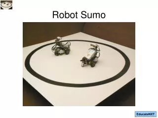
Mini Sumo Electronics Tutorial F09. out LINE. Board Overview Components and Soldering Testing and Debugging General Advice. board OVERVIEW. Custom 2 layer design , updated this Summer Cost per board is about $60-80 w/components depending on manufacturer

E N D
outLINE • Board Overview • Components and Soldering • Testing and Debugging • General Advice
boardOVERVIEW • Custom 2 layer design, updated this Summer • Cost per board is about $60-80 w/components depending on manufacturer • Based around Microchip’s PIC18F4580 microcontroller
blockDIAGRAM I2C Bus Status LEDs Microcontroller (PIC18F4580-I/P) Serial I/O (MAX232N) Programming Interface (ICSP) Sensor I/O Motor Control (2x MC33886)
boardCOMPONENTS Match to stripe on board Schottky Diode (Polar) Capacitor PIC18F4580 Negative Pin 1 Marker LED (Polar) 100 + 2 zeros = 10k Electrolytic Capacitor (Polar) MC33886 Resistor Pin 1 Marker LM1084 Voltage Regulator Friction Lock Header Male Header MAX232N
solderingBASICS • Soldering: Use of a hot iron to melt a tin alloy in order to electrically connect components to a circuit board Image courtesy of SparkFun Electronics
solderingTIPS • Iron temp is usually set to ~70-75 • Make sure you wipe the iron tip on the wet sponge every time you solder something • Components should be flush to the board • Demos will be done in the lab. • Ask us for help if you need it. Hint: You will.
moreHELP • You CAN destroy components and/or parts of the board • You ARE easily burned. Be careful. • Highly recommended set of tutorials + videos: http://www.sparkfun.com/commerce/tutorial_info.php?tutorials_id=96
testandDEBUG • The schematic and layout are on our website. This presentation will be on our website. • You should check our website. • Something will break/be broken • Hardware debugging can be very frustrating.
thereFORE • Test allpower inputs before placing chips into sockets/soldering the MC33886s • Flux remover is your best friend. Flux is a flowing liquid residue from soldering. It’s conductive. Enough said. • Pay close attention to component polarity where applicable. This is how chips explode.
extraPICS • A few of you will blow up your microcontrollers. • Free samples are available from Microchip. You may be interested. • YOU have to order them. (We used ours) • Instructions on our website under articles: http://uwrobotics.uwaterloo.ca/articles/11 • Do this immediately. Shipping takes time.
generalADVICE • Divide up tasks. Work concurrently. • You don’t need the lab to program or sketch drawings. • It’s on YOU to ensure work gets done. • Remember to allocate time for testing. Very few things in engineering work the first time. Especially robots.
questions? Post Production Mods Typical. Welcome to Electronics. Image courtesy of SparkFun Electronics
buildTIME • Starts now. • SOME of you should come with me to the soldering session. • You also have software to write and a chassis to design and build • You should remember to buy batteries. 4 AAs preferably. You may want spares.