Download
1 / 91
920 likes | 1.03k Views
Explore Chapter 3 of ECE200 covering MIPS instructions, ISA motivation, RISC, arrays, pointers, and more. Learn about basic processor operation and ISA design concepts.

E N D
ECE200 – Computer Organization Chapter 3 – Instructions: The Language of the Machine
Homework 3 • 3.2, 3.5, 3.9, 3.11, 3.14, 3.16, 3.19, 3.25, 3.27 • Warning: Some of you will find this to be the most difficult chapter and hardest homework of the course
Outline for Chapter 3 lectures • Basic processor operation • ISA motivation: enabling fast hardware implementations • Reduced Instruction Set Computing (RISC) • MIPS instruction formats and addressing modes • Rundown of MIPS instructions • Procedure call • Arrays and pointers • Assembling, linking, and loading programs • Motorola MCore ISA
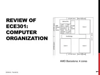
The heart of a modern microprocessor destination operand source operand 1 Load instructions bring data from memory into the register file register file source operand 2 ALU ALU = Arithmetic Logic Unit operation Store instructions store data from the register file into memory Register file holds data to be operated on
Basic processing of an instruction • Instruction fetch • Get the instruction from instruction memory • Instruction decode • Figure out what kind it is and how to control it • Read source operands • Get data to be operated on from the register file • Execute • Do the operation • Write destination operand • Write the result of the operation to the register file
Basic processing of an instruction • Instruction fetch • Get the instruction from instruction memory
Basic processing of an instruction • Instruction decode • Figure out what kind it is and how to control it control logic
Basic processing of an instruction • Read source operands • Get data to be operated on from the register file
Basic processing of an instruction • Execute • Do the operation
Basic processing of an instruction • Write destination operand • Write the result of the operation to the register file
The job of the ISA designer is to… • create an ISA that enables fast hardware designs… • that meet the design constraints (cost, power dissipation, etc.)… • of the targeted market (workstation, handheld, etc.) • Other jobs as well, such as • Simplifying choices for the compiler • Ensuring the longevity of the ISA by anticipating future technology trends
Making computer hardware fast • Computer hardware consists of datapaths and control, each of which may limit machine speed • The datapaths pass the data that is being computed on to the different units • The control steers the data to different units and selects the operation of each unit • Example input select arithmetic logic unit MUX datapath control operation
Making computer hardware fast • Goal #1: fast execution of simple operations • Goal #2: fast access of data from memory • Goal #3: fast fetching and decoding of instructions
Fast execution of simple operations • Many programs contain predominately simple integer operations (e.g., add, and, load, branch) • The results of operations are often used by successive instructions • a + b + c + d • Microprocessor designers make these simple operations as fast as possible and try to set the clock period of the chip to match this speed
Register-register ISA • All operands for arithmetic operations are read from the register file • Register file (32 registers in MIPS) holds data to be executed • Big enough to hold most variables but small enough for a fast clock • Very fast datapath and simple, fast control • Operations which require the result of immediately prior operations can execute on back-to-back clock cycles through an operation called forwarding (Ch 4) destination operand register # destination operand source operand 1 source operand 1 register # register file source operand 2 ALU source operand 2 register # operation
Register-register ISA • add $4, $3, $10 destination operand register # destination operand source operand 1 source operand 1 register # register file source operand 2 ALU source operand 2 register # operation
Making computer hardware fast • Goal #1: fast execution of simple operations • Goal #2: fast access of data from memory • Goal #3: fast fetching and decoding of instructions
Fast access of data from memory • In a register-register machine, load and store operations are used to access data in memory • To access data memory, we need to first calculate the data’s memory address, called the effective address • Addressing modes provide the means for representing offsets, array indexing, pointers, etc. at the assembly language level • The number and complexity of addressing modes is a tradeoff between INST and (CPI,CT) • More, powerful modes reduces INST • Fewer, simple modes simplifies the EA calculation control and datapath, and thus the time required to access memory • The ALU can serve the additional purpose of effective address calculation to save hardware
Addressing mode example #1 • Base mode (also called displacement mode) • Used to access local variables • Example: ld $2, 4 ($1) destination operand destination operand register # source operand 1 source operand 1 register # register file effective address data cache ALU immediate value operation = add
Addressing mode example #2 • Scaled mode • Used to index arrays • Example: ld $2, 4 ($1) [$3] destination operand destination operand register # source operand 1 source operand 1 register # register file effective address source operand 2 data cache + source operand 2 register # ALU x scale operation = add immediate value
Making computer hardware fast • Goal #1: fast execution of simple operations • Goal #2: fast access of data from memory • Goal #3: fast fetching and decoding of instructions
Fast instruction fetching • The Program Counter is a special register that holds the memory address of the currently executing instruction • The PC is normally incremented to point to the next sequential instruction, except in the case of a jump or taken branch • Limiting the way that branches can modify the PC speeds up the calculation of the next PC PC instruction cache logic instruction branch displacement branch condition
Fast instruction decoding • After an instruction is fetched, we parse its fields in hardware (decode it) to determine • The operation to be performed • The location of the source and destination operands • Other instruction-specific information such as • The addressing mode and values (e.g., offset) for memory instructions • Constant values • Decode is greatly simplified (and therefore execution begins sooner) if • All instructions have the same length • There is consistency (regularity) among instruction types in terms of where the fields are located • The number of fields is limited
Reduced Instruction Set Computing • RISC has its roots in • The IBM 801 project started by John Cocke at IBM Research in 1975 • Precursor to the IBM RS/6000 workstation processors which later influenced PowerPC • The Berkeley RISC project started by Dave Patterson in 1980 • Evolved into the SPARC ISA of Sun Microsystems • The Stanford MIPS project started by John Hennessy ~1980 • Hennessy co-founded MIPS Computer • RISC philosophy is that instruction sets should be simplified to enable fast hardware implementations that can be exploited by optimizing compilers • University projects had the added goal of single chip implementation
Original RISC approach • Fixed-length (32 bits for MIPS) instructions that have only a few formats • Simplifies instruction fetch and decode • Code density is sacrificed • Some bits are wasted for some instruction types • Register-register architecture • Also called load-store architecture • Permits very fast implementation of simple instructions • Easier to pipeline (Chapter 6) • Requires more instructions to implement a HLL program • Limited number of addressing modes • Simplifies EA calculation and thus speeds up memory access • Few if any complex arithmetic functions • Instead more, simpler instructions are used
Some recent deviations from RISC • Shorter instructions (16 bits) intermixed with longer (32 bits) • Higher code density for embedded environments • Some complex operations • Multiply-add for DSP and multimedia applications • Experience is that selectively adding some complexity back into the ISA improves performance and/or cost effectiveness
MIPS instruction formats • R-type (Register) • I-Type (Immediate) • J-Type (Jump) 31 26 25 21 20 16 15 11 10 6 5 0 op rs rt rd shamt funct 31 26 25 21 20 16 15 0 op rs rt immediate 31 26 25 0 op target
MIPS instruction formats where • op is a 6-bit operation code (opcode) • rs is a 5-bit source register specifier • rt is a 5-bit (source or destination) register specifier or branch condition • rd is a 5-bit destination register specifier • shamt is a 5-bit shift amount • funct is a 6-bit function field • immediate is a 16-bit immediate, branch displacement, or memory address displacement • target is a 26-bit jump target address • Simplifications • Fixed length • Limited number of field types • Many fields located in same location in different formats
Rundown of MIPS instructions • Computational • R-type and I-type • Load and store instructions • I-type • Jump and branch instructions • R-type, I-type, and J-type • Only dealing with integer instructions for now
Registers in MIPS general purpose registers multiply/divide registers • 32 GPRs • r0 is equal to zero in all MIPS implementations, which makes it easy to… • Load a constant, e.g., addi $2,$0,#3 • Do absolute addressing, e.g., lw $4,1000($0) • r31 holds return address for subroutine returns • All other GPRs are “generic” although software conventions define their usage (discussed later) 31 0 31 0 r0 HI r1 LO . . . program counter register 31 0 PC r30 r31
Registers in MIPS • HI and LO • Hold multiply result (HI holds upper half) • Hold divide quotient (LO) and remainder (HI) • PC holds address of currently executing instruction • Also have a separate set of 32 floating point registers if floating point arithmetic is supported
Computational operands in MIPS • All computations occur on full 32 bit words • Computations are on signed (2’s complement) or unsigned operands (positive numbers) • Example: 1111 1111 1111 1111 1111 1111 1111 1111 is –1 as a signed number and 4,294,967,294 as an unsigned number • Operands are in registers or are immediates • Immediate (constant) values are 16 bits wide • Value is sign extended (most significant bit is replicated in the uppermost 16 bits) before operated on to convert it to a 32-bit operand • Example: 1000 0000 0000 0000 becomes 1111 1111 1111 1111 1000 0000 0000 0000
Computational instructions • Arithmetic (signed, unsigned, and immediate) • add, sub, mult, div • addu, subu, multu, divu • addi • Logical • and, or, nor, xor • andi, ori, xori • Shift (logical and arithmetic) • srl, sll • Shift shamt digits to right or left; put zeros in leftmost positions for srl • srlv, sllv • Shift [rs] digits to right or left; put zeros in leftmost positions for srlv • sral, srav • Same as above except sign-extend the high-order bits
Computational instructions • Set less than (signed, unsigned, and immediate) • Set rd to 1 if condition is met, set to 0 otherwise • Almost always paired with a branch instruction • slt, sltu • Condition is rs<rt • slti, sltiu • Condition is rs<immediate • Load upper immediate (lui) • Shift immediate 16 bits left, append 16 zeros to right, put 32-bit result into rd • Can create a 32-bit constant from lui and ori • Move to/from HI/LO • mfhi, mflo • Put HI or LO register contents into rd • mthi, mtlo • Put rs contents into HI or LO (for interrupt recovery)
Load and store operands in MIPS • Memory operands can be bytes, half-words (2 bytes), or words (4 bytes [32 bits]) • opcode determines the operand size • Number of address bits used is • 32 for accessing bytes • 31 for accessing half-words • 30 for accessing words • Half-word and word addresses must be aligned • Bit 0 must be zero for half-word accesses • Bits 0 and 1 must be zero for word accesses • Load operands can be signed or unsigned 1 byte . . . . . . word effective address 31 1 0 12 12 0 0 memory 8 8 4 4 0 0 byte addresses 1 word
Load and store instructions • lb, lh, lw • Form effective address, get data from addressed memory location, sign extend if lb or lh, load into rt • lbu, lhu, lwu • Form effective address, get data from addressed memory location, zero extend if lb or lh, load into rt • sb, sh, sw • Form effective address, store data from rt (partial if sb or sh) into addressed location • Also load/store instructions for unaligned data
MIPS assembly example • A is an array of words • Starting address of A (memory address of A[0]) is in $4 • Want to perform A[3] = A[0] + A[1] - A[2] • MIPS assembly language: lw $1, 0($4) # A[0] into $1 lw $2, 4($4) # A[1] into $2 add $1, $1, $2 # A[0]+A[1] into $1 lw $2, 8($4) # A[2] into $2 sub $1, $1, $2 # A[0]+A[1]-A[2] into $1 sw $1, 12($4) # store result in A[3]
Branch and jump instructions • Branch instructions test a condition, either • Equality or inequality of rs and rt • beq, bne • Often coupled with slt, sltu, slti, sltiu • or the value of rs relative to zero • bltz, bgtz, blez, bgez • and form the target address by adding the sign extended immediate to the PC • Since all instructions are words, immediate is shifted left two bits before being sign extended • Operation true false test condition PC = target PC = PC+4
Branch and jump instructions • Jump instructions unconditionally branch to the address formed by either • Shifting left the 26-bit target two bits and combining it with the 4 high-order PC bits • j • The contents of register rs • jr • Branch and link and jump and link instructions also save the address of the next instruction into r31 • bltzal, bgezal, jal, jalr • Used for subroutine calls • jr $31 used to return from a subroutine
for loop and if-then-else example • i, j, n are in $1, $2, $3; $4 holds A base address for (i=0; i<n; i++) { if (A[i] < j) A[i]=A[i]*2 else A[i]=A[i]+1 } add $1, $0, $0 # initialize i to 0 Loop: lw $5, 0($4) # A[i] into $5 slt $6, $5, $2 # set $6=1 if A[i]<j beq $6, $0, Else # if not true, do else add $5, $5, $5 # A[i]=A[i]*2 j Exit # skip else Else: addi $5, $5, 1 # A[i]=A[i]+1 Exit: sw $5, 0($4) # store A[i] addi $4, $4, 4 # point to next A[i] addi $1, $1, 1 # increment i bne $1, $3, Loop # loop back if i<n
Special instructions • System call (syscall) • Call OS to perform system services, e.g., printf • $2 contains code specifying the service to perform • breakpoint • Transfer control to exception handler • Useful for debugging • Many instruction extensions have been made to the original MIPS ISA • Branches • System functions • Etc.
Pseudoinstructions • Assembler can create instruction sequences for other common operations • Examples • move $2, $3 • blt $7, $14, Label • li $4, 100 • Many more examples in Appendix A • Do not use these in your assignments!
Register usage conventions • Software conventions for the use of registers ensure that routines developed by different programmers can work together • MIPS assembly convention assigns special names and meanings to the GPRs • Preferred to use symbolic names instead of register numbers
Caveats • Conventions may vary by compiler (SGI/MIPS, gcc, etc.) • The book has taken some liberties in the spirit of simplification (and so will my notes) • So what is presented here (and in the book) may not be 100% accurate in terms of following “MIPS conventions”
MIPS register usage conventions Register name usage 0 $zero always returns zero 1 $at reserved by assembler 2-3 $v0,$v1 value returned by subroutine 4-7 $a0-$a3 arguments passed to subroutine 8-15 $t0-$t7 temps not saved by called subroutine 24,25 $t8,$t9 16-23 $s0-$s7 temps saved by called subroutine 26,27 $k0,$k1 reserve for use by interrupt handler 28 $gp pointer to global area 29 $sp stack pointer 30 $fp frame pointer 31 $ra subroutine return address
Procedure call • To support procedures, we need means for • Passing parameters to the procedure • Transferring control to the procedure • The procedure to use registers and memory without disturbing that of the calling program • Passing results back to the calling program • Returning control to the calling program calling program (1) pass parameters, transfer control (2) save variables, allocate memory for local variables stack procedure (3) execute procedure (4) restore variables (4) pass results, return control
Procedure call • Passing parameters • $a0-$a3 reserved for parameter passing • Additional parameters passed via the stack (later) • Transferring control • jal ProcedureName • Puts PC+4 into $ra ($31) and jumps to address associated with label ProcedureName • Passing results • $v0,$v1 reserved for passing results • Stack used for additional results • Returning control • jr $ra • Jumps to address contained in register $ra
Caller and callee-saved registers • Caller: the procedure that calls another • Callee: the called procedure • Values in registers that are needed by the caller after the callee returns must be preserved • $s1-$s4 must be the same after return from doubleit add $s1, $zero, $zero # initialize i to 0 Loop: lw $t0, 0($s4) # A[i] into $t0 slt $t1, $t0, $s2 # set $t1=1 if A[i]<j beq $t1, $zero, Else # if not true, do else add $a0, $t0, $zero # copy A[i] into $a0 jal doubleit # doubleit performs A[i]=A[i]*2 add $t0, $v0, $zero # copy result into $t0 j Exit # skip else Else: addi $t0, $t0, 1 # A[i]=A[i]+1 Exit: sw $t0, 0($s4) # store A[i] addi $s4, $s4, 4 # point to next A[i] addi $s1, $s1, 1 # increment i bne $s1, $s3, Loop # loop back if i<n
Caller and callee-saved registers • $t0-$t9 are caller-saved registers • Calling procedure must save them before the procedure call if its want the values preserved across the call • Called procedure can use them without saving them first • Used for temporary values that do not need to be saved across a call, or if we use all $s0-$s7 • $a0-$a3 and $v0,$v1 are also caller-saved • $s0-$s7 are callee-saved register • Called procedure must save them before using them • Calling procedure does not need to save them before the call • Used for values that need to be preserved across a call, or if we use all $t0-$t9 • If the caller does not need $t0-$t9, $a0-$a3, and $v0,$v1 to be saved across a call, and the callee does not use $s0-$s7, then none of them need to be saved