Download

1 / 35
350 likes | 373 Views
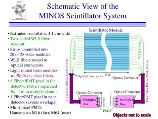
MINOS Detector Scintillator Module Construction Methods. Jim Grudzinski Mechanical Engineer Argonne National Laboratory High Energy Physics division (for the MINOS Collaboration). Some Motivation. The MINOS detector has a very large solid scintillator area-28,000m 2 (0.3kT)

E N D
MINOS Detector Scintillator Module Construction Methods Jim Grudzinski Mechanical Engineer Argonne National Laboratory High Energy Physics division (for the MINOS Collaboration)
Some Motivation • The MINOS detector has a very large solid scintillator area-28,000m2 (0.3kT) • 8x times larger than anything previous (Grand Sasso -3600m2) • This size could only be accomplished with improved strategies • Extruded Scinitillator • High Quality WLS fiber • low cost multi-pixel PMT’s • Efficient and low-cost production techniques
Some Design Considerations • 4445 Modules required • 3782 Far Detector, 4 types plus two mirror images, 20- to 28-strips wide, 8m long • 573 Near Detector, 8 types plus 8 mirror images, 16-, 20-, and 28- strips wide,2-3.6m long • Flexible assembly methods required to accomodate variety in size and geometry • Quality and consistency needed for large scale production • Cost kept down through lower cost student labor • Unskilled (initially) labor
Stamped Aluminum Covers Machined manifold include fiber grooves to maintain minimum bend radius but also compensate for scintillator width tolerance Variable width seal adjusts to completed module width which could is allowed to vary by +/- 10 mm Holes in manifold used for alignment in assembly and surveying during installation Module Parts
Manufacturing Optimizationof MINOS Modules Enabling technologies Driving constraints Component Solution Base manifolds Machined Foamed PVC NC router Cost Size Detail Cost Size Fire safety Manifold covers Sheet metal Laser cutting NC forming Light inj manifs Var width seals Cost Detail Inj molded noryl plastic Mold flow sim CAD opt Light cases Light seal Cost Fab time Size Safety Roll formed sheet metal Custom designed crimper
MINOS Module Assembly Equipment • Scintillator cutting station • Forming Station • Assembly trays • Module curing racks • Fiber gluing machine • Connector flycutter • Module Crimper • Module Source Mapper
Scintillator cutting station • Fixturing to locate cutting guide depending on module type • Cut accuracy +/-1mm over 8000mm.
Module Assembly Trays • 4’ W x 30’ L Aluminum Hexcell sheets, edges filled with body filler • Hexcell provides stiff support while remaining relatively light allowing much structure to be eliminated from moving module storage racks • Fitted with fixturing bushings and vacuum manifolds for assembly • Results in repeatable assembly to within 1mm over 8000mm. • Provide easy means of module transfer between assembly stations/steps • Integral Vacuum ports
Bottom Light Case Forming • Hand slitting tool to compensate for scintillator width variation • Hand forming tools • Table fixturing the same as assembly trays for hole punching
4 indexing shelves Rollers on shelves Overtravel limit switches 120VAC housed in conduit, seal tight , and approved enclosure Racks mounted on Casters for portability Module Curing Racks
Module Curing Racks (cont.) • Screw jacks raise and lower shelves • 4 jacks are coupled to single drive unit • Clamps hold trays in place • Chains,shafts, and couplings fully guarded • Manual motor control with Momentary contact switches
Module manipulation • Module trays moved around individually using shuttle tables or in bulk using the storage racks
Fiber Gluing Machine • PLC controlled semi-automatic operation • Applies epoxy, fiber, and tape in single operation • Operator controls on both sides of carriage • Accommodates 8 different type of module geometry • Fiber and glue dispensing tracks scintillator groove
Operator threads fiber, tape, then starts machine Gluing quality superior to hand gluing Carriage motor, glue pumps, cylinders all controlled automatically by PLC Compliant pushstick key to maintaining fiber low in groove Able to glue 4 modules per day with a single operator Fiber Gluing Machine (cont.)
Connector Flycutter • Diamond bits polish the connector/fiber ends • Converted commercial grinder made low cost high quality solution • Fixturing positively locates the connector
Reflector ends • Near Module detectors have reflector ends allowing single ended readout • Precision Stamped plate provides alignment • Hot knife trims fiber perpendicular • Aluminized Mylar tape attached to fiber using optical epoxy
Module Crimper • Folds over top and bottom light case into labyrinth seal • 9 stations progressively form crimp seal • Mounted to swivel carriage • Carriage manually powered with gear rack and pinion
Detailing and Light Sealing • Light Injection Manifold Applied • Variable Width Seal • RTV, black electrical tape, and aluminum tape used for light sealing joints
Module Mapper • Completely automated • 137Cs Source, 5miCi • Light injection used to calibrate PMT’s • Approx. 40 minutes to map a far detector module (7-8 per shift) • Continuous scan across X-axis, Y-axis incremented in 8cm discreet steps
Results through 2000 modules • Highly consistent results demonstrate quality of the assembly process • <0.2% below 0.5
Soudan Underground Laboratory The Soudan shaft limits objects to a maximum size of 1m by 2m by 9m Slide courtesy J. Nelson Photos by Jerry Meier
Module Storage and Shipping • Shipping crates had to fit in very tight envelope to pass through mine shaft • Fully loaded crates weighed 5500 lbs • Modules had to be securely held through 360 rotation on trip down mine shaft • Separate crates for perpendicular and 45 degree modules • Factories had local storage to optimize trucking • Eight perpendicular crates fit on one flat bed
Module Shipping Essentially no change after delivery
Conclusion • High precision large scale assembly was accomplished using lower cost unskilled labor through creative use of tooling • Assembly trays allowed tight envelope tolerance • Crimping provided reliable and fast light tight seal • Hand forming allowed custom module widths • Automatic mapping required minimal manpower • Laminated assembly technique made stiff modules • Automated Fiber gluing combined with extruded scintuillator produced high quality consistent modules • Resulting Modules show high quality and consistency with 75% of the production complete