Download
1 / 24
250 likes | 543 Views
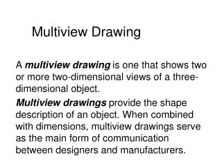
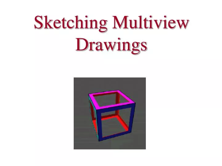
Sketching Multiview Drawings. 1.2 Concepts. Engineers create sketches to quickly record, communicate, and investigate ideas. Pictorials and tonal shading techniques are used in combination to give sketched objects a realistic look.

E N D
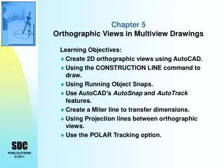
1.2 Concepts • Engineers create sketches to quickly record, communicate, and investigate ideas. • Pictorials and tonal shading techniques are used in combination to give sketched objects a realistic look. • Designers use isometric, oblique, perspective, and multiview sketching to maintain an object’s visual proportions. • A multiview projection is the most common method of communicating the shape and size of an object that is intended for manufacture.
Performance Objectives It is expected that students will: • Identify and sketch construction lines, object lines, and hidden lines. • Sketch an isometric view of simple geometric solids. • Understand how an oblique view differs from an isometric view. • Sketch one-point, two-point, and three-point perspectives of simple geometric solids. • Sketch multiview drawings of simple geometric solids. • Determine the front view for a given object.
Words of the Day • Orthographic drawings – drawings where three views of an object are drawn in perpendicular planes to one another. • Isometric drawings - drawings that show multiple sides of an object in one view; it forms 120 degree triangles. • Proportion - Comparative relationship of two objects regarding size.
Pictorial Drawings • There are two types of pictorial drawings: ObliqueIsometric
Isometric Drawings • Isometric means equal measure. • Isometric Drawings are drawn at 30 degree angles from the x axis. • The edges that converge will appear as 120 degree angles
Oblique Drawings • Oblique drawings show multiple views of the object but one of the axes is on a 90 degree angle and the other is on a 45 degree angle. • An oblique starts with a straight-on view of one of the object’s faces, which is often the front view. 45°
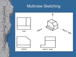
Orthographic Drawings • There are typically 3 views displayed in an Orthographic drawing • Top • Front • And either the Right Side • Or the Left Side
Orthographic Views • Notice that the Top View is positioned above the front and they are aligned • The Right Side view is positioned to the right of the front view and also aligned T F R.S.
Orthographic Views • The most important view is the Front View • You must determine which will be the front • Choose the view that is the longest and the one with the most detail T F R.S.
Object Descriptors All three-dimensional objects have width, height, and depth. • Width (side-to-side) • Height(top-to-bottom) • Depth (front-to-back)
Object descriptors: Width Height Depth
Orthographic Projection Orthographic projectionis a technique that is used to create multiview drawings. The best way to understand orthographic projectionis to imagine an object contained inside a glass box.
Orthographic Projection There is a total of six glass walls surrounding the object. Each wall represents a projection planeonto which a two- dimensional object view will be created.
Orthographic Projection Start by focusing only on the front projection plane. A person standing in front of the object would see only the five corners identified in black. 2 3 1 4 line of sight at 90° angle to projection plane 5
Orthographic Projection Projection linesare used to project each corner outward until they reach the projection plane.
Orthographic Projection The visible edgesof the object are then identified on the projection plane by connecting the projected corners with object lines.
Orthographic Projection The orthographic projectionprocess is then repeated on the other projection planes.
Completed Multiview Drawing Isometric (Pictorial) Orthographic
Each of the blocks at right has the same footprint. What do their top views look like?
Proportion Good sketch Good sketching should be proportional. Poor sketch