Download

1 / 42
470 likes | 857 Views
Multiview Drawing. 5.00 Demonstrate orthographic projection techniques and principles as they apply to multiview drawings. Multiview Drawing. 5.01 Explain the concepts and principles underlying the creation of multiview drawings. Multiview Drawing.

E N D
Multiview Drawing 5.00 Demonstrate orthographic projection techniques and principles as they apply to multiview drawings.
Multiview Drawing 5.01 Explain the concepts and principles underlying the creation of multiview drawings.
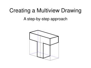
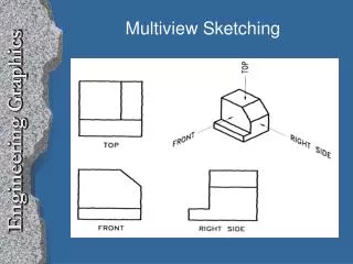
Multiview Drawing • Another name for orthographic projection is multiview drawing • Involves visualization and implementation • Ability to see clearly in the mind’s eye an object • Process of drawing the object
Multiview Drawing • A system that allows you to make a two-dimensional drawing of a three-dimensional object
Viewing Objects A box is formed by six mutually perpendicular planes of projection that are located around the object
Lines are formed on the planes by projecting the edges of the object onto the planes These images are called “views” There are six views formed by the planes of a box Viewing Objects
Viewing Objects • Unfolding the box produces an arrangement of the six views
Angles of Projection • First-angle projection • Used by many European countries • Object is projected onto planes from the first angle or quadrant • Front view projected to vertical plane • Top view projected to horizontal plane • Left-side view projected to profile plane
Angles of Projection • Third-angle projection • Standard for the United States • Third quadrant is used for projection • Front view projected to vertical plane • Top view projected to horizontal plane • Right-side view projected to profile plane
Viewing Objects • Each view is placed in a constant location relative to the other views • Each view must be placed in its correct position • Views and features must be aligned
Choosing Views • Most commonly used views • Front View • Top View • Right Side View • Most descriptive view is typically designated as the Front View
Choosing Views • Complex objects require three views to describe its shape • Simple objects can be described with two views • Ex: Soda Can • Thin objects can be described with only one view • Depth is given in a note • Ex: Erasing Shield
Choosing the Views • Objects described in two views • Third view would add nothing to the description of the object • Carefully select views to describe shape of objects accurately
Curved Surfaces CYLINDER CONE • Some curved surfaces do not show as curves in all views WHEEL FRUSTRUM
Object Dimensions • All objects have 3 dimensions • Height • Distance from top to bottom • Width • Distance from side to side • Depth • Distance from the front to back
Object Dimensions • Front View • Shows width & height • Top View • Shows width & depth • Side View • Shows height & depth
Drawing Views of Objects • Depth can be projected between views by using a 45° miter line
Line Types - Visible • Edges that can be seen in a given view are VisibleorObject lines • Visible lines are thick and dark • .028” or .7mm (your pencil) • F or HB lead
Line Types - Hidden • Edges that cannot be seen from a given view are indicated by Hiddenlines
Line Types - Hidden • Drawing hidden lines • .125” (3mm) long dashes-- (1/8”) • .0625” (1mm) spaces between-- (1/16”) • Thin: .020” (.5mm) (BLK mech. pencil) • Dark: F or HB lead
Line Types - Hidden • Follow rules for hidden line placement • Alphabet of Lines • Drawings produced with CAD may violate hidden line rules
Line Types – Center • Center linesindicate axes of symmetry
Line Types – Center • Perpendicular lines for circular objects • Small dashes cross at the center point of feature • One center line drawn to indicate longitudinal axis of cylinder or hole
Line Types - Center • Draw center lines using a series of long and short dashes • .125” (3mm) short dash @ the center • .75”- 1.5” (20mm-40mm) long dash • .0625” (1mm) spaces between dashes • Thin: .02” (5mm) (BLK mech. pencil) • Long dash extends .125” to .25” beyond feature, be consistent.
Precedence of Lines • Which line should be drawn when two lines coincide (fall in same place)? • Visible line coincides with hidden or center line • Visible line is shown • Hidden line coincides with center line • Hidden line is shown
Placement of Views • Views should be visually balanced within the working space
Steps for Centering a Drawing • Draw border and title block using light construction lines • Draw diagonal lines from corners of border
Steps for Centering a Drawing • Add: • Width 5.13 • Space 1.50 • Depth 2.00 • Horizontal 8.63 • Height 3.00 • Space 1.50 • Depth 2.00 • Vertical 6.50
Steps for Centering a Drawing • Draw a box the size of all views • Measure from the center: • Half the width • Half the height
Steps for Centering a Drawing • Draw in views using light construction lines
Adding Details • Add holes and features • Transfer horizontal and vertical features • Use miter line to transfer depth
Multiview Drawing 5.02 Visualize objects and views
Straight Edges • Edges that are perpendicular to a plane of projection appear as a point 1 2 3
Straight Edges • Edges that are parallel to a plane of projection appear as lines • Edges that are inclined to a plane of projection appear as foreshortened lines
Curved Edges • Curved edges project as straight lines on the plane to which they are perpendicular • Curved edges project as curved lines on the planes to which they are parallel or inclined
Normal Surfaces Normal surfaces appear as an edge in two opposite principal views, and appear a surface in all other principal views.
Inclined Surfaces • Inclined surfaces appear as an edge in two opposite principal views, and appear foreshortened (not true size) in all other principal views.
Oblique Surfaces • Oblique surfaces do not appear either as an edge or true size in any principal view.
Intersections & Tangencies • Where a curved surface is tangent to a plane surface, no line should be shown where they join
Intersections & Tangencies • Where a plane surface intersects a curved surface, an edge is formed
Intersections & Tangencies • Where the plane surface is horizontal or vertical, exceptions to these rules may occur