Download
1 / 45
920 likes | 2.75k Views
A-scan Biometry. Introduction:- Ophthalmic ultrasound uses the reflection of high frequency sound waves to define the outlines of ocular and orbital structures and to measure the distance between them.

E N D
A-scan Biometry Introduction:- Ophthalmic ultrasound uses the reflection of high frequency sound waves to define the outlines of ocular and orbital structures and to measure the distance between them. • A-Scan biometry is to determine the power of the intra ocular lens, that replaces the natural lens during cataract surgery. • A-Scan biometry is also called as axial length measurement scan. This measurement is combined with Keratometric readings to obtain the IOL power. • Error of 0.4mm in the measurement of axial length may result in a one diopter change in calculated IOLpower.
Physical principles • The A-scan probe contains a ultrasonic transducer that projects a thin sound beam that travels through liquid or tissue. • Ultrasound waves do not travel through air. • The frequencies most often employed for diagnostic work are between 2.5 MHZ and 20 MHZ. Higher the frequency greater the resolution. • Although increasing the frequency increases the resolution,it simultaneously decreases the depth of penetration of the sound. • When the sound beam encounters the interface of a substance that is dissimilar from the substance it is traveling through,part of the sound beam energy is reflected , and part of the sound energy projects through the new substance.
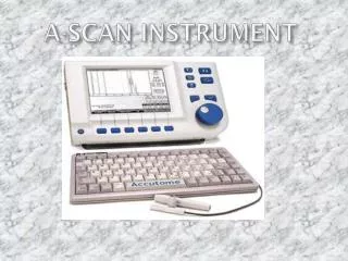
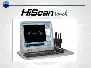
PROCEDURE: • A probe is placed on the patient’s cornea. • The probe is attached to a device that delivers adjustable sound waves. • The measurements are displayed as spikes on the screen of an oscilloscope (Visual monitor). • The appearance of the spikes and the distance between them can be correlated to structures within the eye and the distance between them.
Probe positioning: • The probe lightly touches the cornea and is positioned, such that the barrel of the probe is aligned with the optical axis or visual axis of the eye. • The operator aims the probe towards the macula of the eye. • Alignment with the optical axis will be indicated by high lens spikes and a high retina spike on the scan graph.
In the manual mode the operator will have to freeze the scan with a foot pedal when an acceptable scan is obtained. • The gain should be adjusted high enough such that the spikes can be maintained above the threshold level needed for an automated acquisition of the scan if this feature is used. • The gain should be low enough to allow the operator to visually maximize the spike height during probe alignment.
The scan of phakic eye • It shows anterior lens spike(B),the posterior lens spike(C),and the retina spike (E), the probe tip / cornea spike is represented by(A). • These spikes should be tall and steeply rising.The retina spike should not have smaller spikes immediately in front of it.(D) • The retina spike should be followed by tall scleral spike (F) and spikes from the orbital fat layer of the orbit(G).A scan without orbital fat spikes may indicate that the beam is striking the optic nerve instead of the macula.
The scan of an aphakic eye • It will either have no lens spikes,(or) it will have one lens spike (A) that represents an intact posterior lens capsule. ( C ) • Be sure to use the aphakic mode of the A-scan instrument. • The velocity of sound will be different because the beam is not passing through the lens. • A velocity of sound of 1532m/s is typically used for aphakic measurements.
Pseudophakic scan • If one is pseudophakic, A-scan and K-readings should be done for both the eyes before calculating the IOL power for the eye required. • Since both eyes have similar measurements in most people, this provides a double check of the measurement. • It is some times necessary to replace an IOL that was inserted many months or years ago. Even if you have IOL specifications and measurement information from the previous surgery, its nice to have the confirmation of a current measurement.
Maintenance of an Instrument • It is done by, • General inspection • Calibration check • Sensitivity test • Cleaning • Storage.
Measuring Gates • A-scan instrument calculate measurements by means of electronic measuring ‘gates or lights’. This instruments has two gates, • One for the cornea spike. • One, that the retina spike must come within. • The instrument to the right has measuring lights that attach to the cornea, lens, and the retina spikes. • Errors may occur if cataract formation results in irregular inter faces within the lens that create extra lens spikes. • This will result in a very short measurement because the total length is figured from the first light to the last light.
Corneal Compression • Since ultra sound does not travel through air the A-scan probe must come into contact with the cornea either directly or through a liquid. • If undue pressure is applied on the cornea, the axial length measurment may be falsely too short. • It can be monitored by observing the anterior chamber depth, read out by an instrument. • Most eyes will have an ACD readings between 2.5 to 4.0mm. • The corneal compression error factor can be avoided by using the immersion technique.
Reproducibility • Reproducibility is an indicator of accuracy: • This means being able to take four or five consecutive measurements with consistent appearance, ACD and total length results. • A commonly accepted level of reproducibility in terms of total length is to have several measurements within 0.20mm of each other.
IOL Power calculation Introduction:- • The importance of accurate IOL power implant power calculation has increased with the development of improved astigmatism control, and surgeon expectations. • Precise biometric measurements of preoperative axial length,corneal curvature are the corner stones of this system.
CLASSIFICATION OF IOL POWER CALCULATION • Methods based on basic refraction. • Methods based on measurements like axial length,corneal curvature. • Theoretical formulas. • Regression or empirical formulas. • Combination of both.
A-SCAN METHODS There are two types, Hand held Method:- Performed by using hand held ultra sound transducer probe. • Disadvantage is, • Compression of cornea • In probe alignment of the probe attribute to accurate measurement of the eye. • Stand held Method:- Probe is fitted in place of Tonometer prism in Tonometer slit lamp models. • Immersion Technique:- Also called water bath method, the patients is supine and ultrasound probe is suspended in fluid filled scleral cup placed over the eye.
Regression Formula • SRK Formula P = A – 2.5 L – 0.9K. P = Implant power to produce emmetropia (diopter). L = Axial length. K = Average Keratometry Readings. A = Specific Constant for each lens types.
AMMETROPIC CALCULATION • The SRK emmetropia calculation uses the refraction factor (RF) of 1.5Dsph. But when targeting for emmetropia of greater than 1.0Ds use the following RF’S. • RF of 1.25 if emmetropia power >14D. • RF of 1.0 if emmetropia power <=14D Formula used for this, IOL = P – ( RT + RF ) IOL = Power of the needed to produce ammetropia. P = Power from SRK formula. RT = Post operative refraction needed. RF = Refraction Factor.
Factors Affecting IOL Power Calculation 1. Axial Length measurement:- Accurate measurement of distance from the corneal cortex to vitreo – retinal interface along the visual axis is essential for the accurate IOL power calculation. 2. Ultrasound Velocity:- • Since the axial length measurement depends on time it takes for the emitted sound beam to reach the vitreo retinal interface and return, the velocity of sound through various structure like aqueous, vitreous, & lens is important. • The accepted average velocity of sound is 1532m / sec in aphakic eyes and 1550m / sec for cataract eyes. • But in pseudophakic eyes the velocity depends on velocity in PMMA, central thickness of IOL in situ and velocity in aqueous & vitreous.
3. Axial length correction for retinal thickness:- The axial length measured doesn’t take into account the distance from the vitreo retinal interface to the visual cell layer, that is estimated to be from 0.15 to 0.5mm. 4. Keratometry :- Failure to calibrate the eye piece leads to error , this can translate to 0.90D error in IOL power calculation. 5. Estimated PO ACD :- (Post operative Anterior chamber depth) ACD = AL / 23.45 X ACD (3.42m). 6. Surgical Techniques:- Measurement of lens in bag places lens further back decreasing the effective power of lens,there is usually a loss of 0.5D to 1.5D.
Errors IOL Power Calculation • It can be categorized into 3 groups, • Measurement errors : 43 – 67 % of errors. • Errors from insufficiencies of the formula. • Errors in prediction of surgical effect, post operative astigmatism and site of lens.
Calculation of Individual A Constant A 1 = 1+ ( RA x RF ) + 2.5 x L + 0.9 x K – C A1 = Individual A Constant. L = Axial Length. K = Average Keratometry. ( D ) I = Power of lens implanted. ( D ) RA = Actual Post operative spherical equivalent. ( D ) RF = Refraction factor. C = Short & long eye Correction.
Measurement errors • It can be prevented by A-scan data. The following guidelines can be followed. 1. Always measure both eyes. 2. Indications for repeat scans • Axial Length < 22.0mm or >25.0mm. • Average corneal power < 40 and > 47D. • Calculated implant power is more than 3D from the average for the specific IOL style used. • Difference between the eyes. • Average correct power > 1 D. • Axial Length > 0.3mm. • Emmetropia implant power > 1 D. 3. Check the position of the measuring gates light on the display.
Characteristics of quality A –Scan Technique 1. 5 Principle echo spikes are present, • Corneal. • Anterior chamber. • Posterior camber. • Retina. • Sclera & orbital flat. 2. Echo heights are adequate if anterior lens echo is 90% or more of maximum height. Posterior lens echo is between 50% & 75% of maximum. • Retinal echo is 75% or more of maximum echo rise angle must be clear. The take off of the retinal spike must be clean and forms a 90° angle from the lease line.
IOL Power calculation in special situation • IOL calculation following Refractive surgery. • IOL in silicon oil filled eyes.
1. It can be done by two methods depending on the amount of refractive error. • Mild to moderate Myopia:- • Corrected by Radial Keratometry ,postoperative Keratometric and axial length data can be used directly. • High Refractive error :- • Corrected by Radial Keratometry or other methods of refractive surgery may cause an error in IOL calculations by providing inaccurate Keratometry data. • In this case IOL power is calculated using original refraction & Keratometry data. The difference between original refraction and the current refraction is determined. • If the patient was myopic this difference in refraction was added to previously calculated IOL power. • If Patient was Hypermetropic subtract this difference.
Biometry in silicon oil filled Eye. • The echographically measured axial length of a eye is greater in the presence of silicon oil. • This is because speed of sound in silicon oil ( 987m / s in silicon oil of viscosity 1000 centistokes) is slower than in vitreous humour ( 1532 m/s). • Theoretically this speed of sound in silicon oil (viscosity 1000 centistokes) compared with the speed of sound in vitreous humour decreases by a factor of 0.64mm. • It is therefore possible to calculate the true depth of the vitreous cavity ( VCD oil x 0.64) = True Axial length.
AL without oil = ACD oil +LT oil+ [VCD oil x (sound vel oil /sound vel in vitreous) ]. • AL With out oil = Axial Length of vitrectomised eye (tissue AL) • Al oil = Measured Axial Length in presence of silicon oil. • ACD oil = Anterior chamber depth in presence of silicon oil. • LT oil = Lens thickness in presence of silicon oil. • Sound velocity in oil = Velocity of sound in silicon oil (1000 cs) 987m/s. • Sound vel vit = Velocity of sound in vitreous (1532m/s). • SRK/T – Formula was used to compare the measured power of IOL and the estimated power of IOL. Conversion factor of 0.71 is used when ACD,LT,and VCD are not known. This Conversion factor can be used for silicon oil of viscosity 1300 centistokes.
Selection of IOL Power 1. Monocular Hypermetropia:- Patient alternates this one can ignore anisometropia and aniesokonia, & reduce the pre existing hypermetropia. 2. Bilateral strong Hypermetropia :- • Pseudophakic eye should not be made emmetropic because one might introduce greater degree of anisometropia . • In this case standard lens should be implanted and stronger convex lens placed in front of operated eye will magnify the retinal image by 4% & decrease anisometropia. 3. Bilateral emmetropia and unilateral implantation and implant standard lens creating a mild myopia , thus patients can use the other eye for distance and the operated eye for near. 4. If primary refraction of one eye is mild to moderate myopia around – 2.0 D and other eye is emmetropic. It is advantage and ideal lens should be implanted.
5. If both eyes are myopic with monocular cataract, implanting emmetropic lens will induce greater anisometropia.Hence some degree of residual myopia is desired. 6. In binocular cataract aim for postoperative emmetropia. In case of BSV keep one eye slightly myopic & other emmetropic. 7. In Primary myopia of more than - 7.0D, eye can be made aphakic. • So visualization of peripheral fundus become difficult during prophylactic photocoagulation and RD surgeries due to refraction from IOL Hindrance of pupillary dilatation may occur due to synechiae formation. • Correction of high myopia with low power IOL have shown good results.
Analyzing and correcting power calculation mistakes • If the postoperative refraction is highly different, lens exchange should be done. • If the IOL power is correct, consider posterior staphyloma or IOL dislocation. • The determination of power of implant in situ can be done as last resort.
Factors to Consider for IOL material • The type of material is important because the velocity of sound is a function of the material that the sound is passing through. • A-Scan does not actually measure length, they measure how long it takes a sound beam to bounce off an object ( Anterior lens, Posterior lens,and Retina) & return to the probe. • The instrument is pre programmed with the velocity of sound factors for the aqueous, the lens material, and the vitreous.
PMMA protocol : (Polymethylmethacrylate) • Sound travels faster through PMMA than it does through the natural lens. • If a pseudophakic mode is not available,you can measure the eye in the aphakic mode and add a standard compensating factor of 0.4mm to the resultant axial length. Silicon protocol: • Silicon IOL’s are foldable. Sound travels much slower through a silicon lens than it does through the natural lens. • If not taking this in to account could result in a –3.0D post - op refractive error. • If your biometer does not have a pseudophakic or silicon mode, use the aphakic mode and subtract a compensation factor of 0.8mm.
Acrylic protocol: • Sound travels faster through acrylic than it does through the natural lens. • If biometer does not have an acrylic mode,use the aphakic mode and add a compensation factor of 0.2mm.
Introduction • Keratometry (or) ophthalmometer . • Keratometry is the measurement of a patients corneal curvature . • It provides on objective,quantitative measurement of corneal astigmatism,measuring the curvature in each meridian as well as the axis. • Keratometry is also helpful in determining the appropriate fit of contact lens . • To measurement the corneal dioptric power. • The measurement of the curvature of the anterior corneal surface by using the first Purkinje image.
Keratometer: • Determines corneal curvature by measuring the size of a reflected “mire”. • Doubling of image avoids problems from eye movements. • Radius scale is exact. Diopter scale is derived from the radius using the formula for surface power D= (n-l)/r,where n=1.3375,an empirically derived “standardized”refractive index for the cornea. • Keratometer measures only the central 3mm of the corneal diameter.
Principle of Keratometry • It measure the size of image reflected from corneal surface, because cornea acts as convex mirror. • When an object is in front of the cornea a virtual image is seen inside the convex mirror (cornea). The size of the image depends on, • The distance of the object and • The curvature of the cornea for a fixed distance of the object the size of the image depends on the curvature of the cornea. • Similarly for a given size of the image distance of the object is different depending on the curvature of the cornea.
The object used is an illuminated circle with plus and minus rings as shown in figure. • The two prisms inside the instrument give two additional one displaced horizontally and another displaced vertically. Three images are seen as in figure. • While taking the reading the pluses and minuses coincide. This is achieved by moving the keratometer with the object forward or backward in front of the eye. • When coincidence takes place the size of the images of fixed value. The distance of the object is different for different curvatures. The instrument is calibrated. As the drum rotate the distance varies.
Parts of keratometer • Telescope • Eye piece at one end (near to examiner) • Objective (near to patient) • Knobs for adjustment of vertical and horizontal curvature on the telescope. • Knobs adjusting height of telescope. • Chinrest-adjusting knobs. • Bulb for illumination. • Knob for focusing of mires. • Model cornea with occluder.
Performing Keratometry • Looking the through the eye piece of the keratometer,use the eye piece to focus the reticule (cross hair) in the same way as for the lens meter. • The patient can comfortably put the chin and forehead on the appropriate rests. • Use the occluder attached to the keratometer to cover the eye not being measured. • Then use the height adjustment knob of the keratometer to position the light reflections at the level of the cornea.
To obtain proper focus, rotate the focus knob until the bottom-right circles converge to form a fused image.(fig) To locate the proper axis, rotate the keratometer until the pluses between the two bottom circles are in the same plane.(fig)