Download
1 / 35
360 likes | 402 Views
Static and Current Electricity. Electrodynamics the study of electrical charges in motion. Electrostatics the study of electrical charges at rest. Two opposite types of charge exist, named positive and negative by Benjamin Franklin. Charge is a property of matter.

E N D
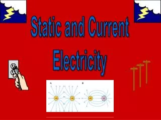
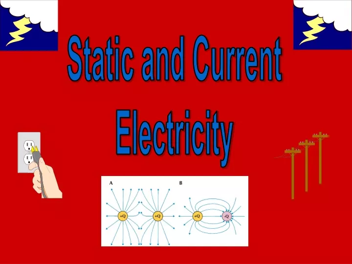
Static and Current Electricity
Electrodynamics the study of electrical charges in motion Electrostatics the study of electrical charges at rest Two oppositetypes of charge exist, named positive and negative by Benjamin Franklin. Charge is a property of matter.
Charged particlesexist in atoms. Electronsare responsible for negative charge; protons for positive charge; neutrons have no charge. Small amounts of ordinary matter contain incredible amounts of subatomic particles!
Conductor material that allows charges to move about easily link Insulator material through which charges will not easily move link Basic Law of Electrostatics Like charges repel; unlike charges attract Link
Click here to view a simulation of the behavior of pith balls in the vicinity of charged rods. See a movie here.
Click hereto read about charging objects by friction. View a simulation of charging a balloon by rubbing it on your hair and then sticking it to a neutral wall here. Learn all about Ben Franklin and his work with electricity here.
charging a rod and electroscope positively and negatively by conductionand induction When charging by conduction, the rod touches the electroscope. The electroscope gets thesame chargeas the rod. When charging by induction, the roddoes not touchthe electroscope. The electroscope gets theopposite chargeof the rod.
Go here , here, here, and here to view simulations of charging an electroscope. Read more here.
COULOMB’S LAW The force between two charged objects is directly proportional to the product of their charges and inversely proportional to their separation distance squared. link1, link2, link3, link4, link4
In equation form: q1 q2 = F k d2 F is the force of attraction, measured in NEWTONS, between charges q1 and q2 k is the Universal Electrostatic Constant, equal to 9.00 x 10⁹ Nm2/coul2 q1 and q2 are the attracting charges, measured in Coulombs d is the distance between the charges, and is measured in METERS
The SI unit of charge is the Coulomb, named in honor of Charles Augustin Coulomb. 1 C = charge on 6.25 x 10¹⁸ electrons (or protons) 1 e- = 1.60 x 10⁻¹⁹Coul = elementary charge Electric force is a vector and must be treated as such.
Electric Fields An electric field exists in a region if space if a charge placed in that region experiences an electric force. The magnitude of an electric field at any given point is defined to be the ratio of the force on a charge at that point to the amount of charge. E = F/Q Electric field strength has units of Newtons/Coulomb (N/C).
The directionof the electric field at any point is defined to be the same direction as the direction of force on a positive test charge placed in the region at that point. Field lines point away from positive and toward negative charges.
Click here to view a simulation showing the magnitude and direction of the electric force on a test charge when placed near other charges. Click here to view a simulation of a charged particle moving through a region occupied by other charges.
Electric Potential Difference the change in electric potential energy per unit charge V=W/Q The SI unit of electric potential difference is the VOLT, named in honor of Alessandro Volta. One VOLT is the electric potential difference between two points when one Joule of work is done in moving one Coulomb of charge between the points.
electric cell - a device that converts one form of energy to electrical energy Chemicalcells convert chemical energy into electrical energy. Chemical cells can be “wet” or “dry”.
Solarcells convert light energy into electrical energy. A generator converts mechanical energy into electrical energy. battery - two or more cells connected in series or in parallel
the flow of charged particles; can be positive or negative, but usually negative (electrons) through a conducting metal
Electric current is measured in Amperes, in honor of Andre Marie Ampere. One Ampere is the flow of one Coulomb of charge per second. 1 Amp = 1 Coulomb per second = 1 C/s I = Q/t
Ammeter a device that measures current Voltmeter a device that measures electric potential difference
power = work/time = (work/charge).(charge/time) =electric potential difference.current P (Watts) = V (Volts).I (Amps)
Analogies of simple circuits are these links: Water circuit analogy link Air flow link Various link Teaching with Analogies link1, link2
Resistance determines the amount of current flow = the ratio of potential difference to current V The SI unit of resistance is the Ohm, W, named in honor of Georg Simon Ohm. R = I One Ohm of resistance is the resistance such that one Volt of potential difference is needed to obtain a current of one Amp.
The resistance of a circuit element depends on: 1. the length of the conductor as length increases, resistance increases proportionally 2. the cross-sectional area of the conductor as area increases, resistance decreases proportionally 3. the resistivity of the conductor as resistivity increases, resistance increases proportionally
Resistivity The resistivity, r, of a conductor is equal to the resistance of a wire 1 cm long and having a cross-sectional area of 1 cm2. l r R = A R = resistance, measured in Ohms r = resistivity, usually in units of W.cm l = length, measured in cm A = cross-sectional area, measured in cm2 Investigate resistivity here
Ohm’s Law The ratio of potential difference to current is constant. If R = V/I is a constant value for a given resistor, then that resistor is said to obey Ohm’s Law. Click here and here to link to pages describing resistor color codes.
Many circuit elements do not obey Ohm’s Law. Resistors that get hot, like light bulbs and heating elements, do not keep a constant resistance. Resistance generally increases as objects become hotter. Click here and here to run simulations of Ohm’s Law.
Resistor Circuits Series 1. total resistance is the sum of the separate resistors RT = R1 + R2 + R3 + ... 2. current is the same through each resistor IT = I1 = I2 = I3 = ... 3. total potential difference is the sum of each VT = V1 + V2 + V3 + ... In other words, in a series circuit, resistance and voltage add, but current stays the same.
P, W R, W V, V I, A E = 12 V 8.0 R1 2.0 R1 R3 R2 5.0 R3 RT = R2 VT = IT = PT =
P, W R, W V, V I, A E = 12 V 8.0 R1 6.4 0.80 5.1 2.0 1.6 0.80 1.3 R1 R3 R2 5.0 4.0 0.80 3.2 R3 RT = 15 Ω R2 VT = 12 V IT = 0.80 A PT = 9.6 W
Parallel 1. reciprocal of the total resistance is the sum of the reciprocals of the separate resistors 1/RT = 1/R1 + 1/R2 +1/R3 + ... 2. total current is the sum of the current through each resistor IT = I1 + I2 + I3 + ... 3. potential difference is the same across each resistor VT = V1 = V2 = V3 = ... In other words, in a parallel circuit, resistance adds as reciprocals, voltage stays the same, and current splits.
P, W R, W V, V I, A E = 12 V 12 R1 8.0 R2 R1 12 R3 R2 RT = R3 VT = IT = PT =
P, W R, W V, V I, A E = 12 V 12 12 1.0 12 R1 1.5 8.0 12 18 R2 R1 12 1.0 12 12 R3 R2 RT = 3.42 Ω R3 VT = 12 V IT = 3.50 A PT = 42 W
Kirchhoff’s Rules Loop Rule: The sum of the potential differences around any closed circuit loop is zero. Junction Rule: The sum of the currents into any circuit junction is zero. Go to link1, link2, link3, link4, link5, and link6 to view pages and simulations examining Kirchhoff’s Loop and Junction Rules.
The sites linked here and here (click on “Circuit Construction Kit”) allow you to build and test your own series, parallel, and combination circuits. For a complete interactive tutorial on electricity and magnetism, go here.