Download
1 / 21
220 likes | 418 Views
4. hf. NETLOGIC. A BRIEF INTRODUCTION TO FIELDBUS. TRADITIONAL CABLING SYSTEM . PLC. 1. 2. 3. 4. 5. 6. 7. 8. 9. 10. TERMINAL BOARD. FIELDBUS SYSTEM. PLC MASTER. OUTPUTS. I/O SLAVE. CAMPO. FIELD. INPUTS. FIELDBUS COMMUNICATION. NETWORK INPUTS (ALL) POLLING.

E N D
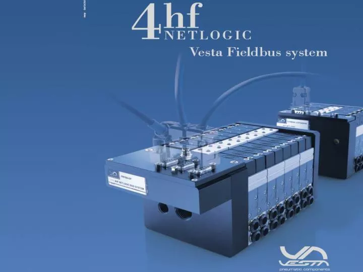
4 hf NETLOGIC A BRIEF INTRODUCTION TO FIELDBUS
TRADITIONAL CABLING SYSTEM PLC 1 2 3 4 5 6 7 8 9 10 TERMINAL BOARD
FIELDBUS SYSTEM PLC MASTER OUTPUTS I/O SLAVE CAMPO FIELD INPUTS
FIELDBUS COMMUNICATION NETWORK INPUTS (ALL) POLLING I/O SLAVE (1) MASTER Output 1 Completed Communication (with address) OUTPUT Order: Slave address (2) Output address (3) Output 2 Each Inputs has: Slave address(2) Input address(1), (2) Master receives Addressed Inputs From the field (input 1, slave 2) I/O SLAVE (2) Output 3 SLAVE NODE Input 1 Input 2 I/O SLAVE (3)
4 hf NETLOGIC FIELDBUS FEATURES
FIELDBUS FEATURES • no input & output cabling to PLC • each slave node needs to be addressed • communications diagnostic available • easy network plug & play expansibility • high number of I/O through a single PLC • guaranteed transmission speed • PLC is always isolated from the field • (PLC supplies the field-bus only)
4 hf NETLOGIC Vesta Fieldbus
4 hf NETLOGIC I/O SLAVE NODE OUTPUT = 4HF SOLENOIDS INPUT = 24V DC DIGITAL SIGNALS
THE SYSTEM VESTA SLAVE NODE (UNCABLED Input e Output) CABLES WITH PLUGS Snap M8 NON CABLED PLC
INTERFACES 24V DC POWER SUPPLY MASTER PLC INTEGRATED SLAVE
4 hf NETLOGIC 4hfNETLOGIC ELEMENTS FEATURES
I/Os Outputs (solenoids) max = 128 Inputs max = 128 HEAD ISLAND Up to 32 Solenoids (16 valve stations) EXPANSION ISLAND Up to 16 solenoids (8 valve stations) Up to 6 expansion islands (32+6x16=128 solenoids) DIGITAL INPUTS BOX (24V DC) Up to 8 inputs Up to 16 Input BOXES (8x16=128 Input)
VESTA SLAVE NODE EXAMPLE Y cable for input boxes connection Y cable for expansions connection
ADDITIONAL OUTPUTS ADDITIONAL 24V DC POWER SUPPLY SUB-D 9 PLUG FOR EXPANSION ISLANDS N°8 DIGITAL OUTPUTS SNAP M8 CONNECTOR 10Watt FOR OUTPUT
DIAGNOSTIC MIF CABLE (MONITOR INTERFACE) PC NODE ADDRESSING NODE DIAGNOSTIC (ADDRESS, N° OUTPUT, N° INPUT) REMOTE CUSTOMER SUPPORT INTERNET
SUPPORTED PROTOCOLS Ethernet IP, Modbus TCP
4 hf NETLOGIC 4hfNETLOGIC FEATURES
4 hf NETLOGIC • EASY NODE ELEMENTS CONNECTION • (EXPANSIONS, DIGITAL INPUTS BOXES) • WITH PLUGGED CABLES (PLUG & PLAY). • SERIAL COMMUNICATION AMONG 4HF • NETLOGIC AND NODE ELEMENTS. • AUTOMATIC I/O ALLOCATION TO THE • 4HF NETLOGIC CHIPSET • EXPANSIONS & DIGITAL INPUTS BOXES • ARE 4HF NETLOGIC SERIES ONLY
4 hf NETLOGIC • MAX 128 OUTPUT, MAX 128 INPUT • MAX CABLES LENGHT (INPUTS & EXP.) = 5 M • MAX SPEED AVAILABILITY FOR EACH • PROTOCOL • NODE DIAGNOSTIC THROUGH MIF CABLE • CE MARKING (89/336/CE) • WORKING TEMPERATURE = -10°/ +50° C
VESTA AUTOMATION S.R.L. Via Martiri di Belfiore, 69/A 45100 ROVIGO, ITALY Web: www.vesta.it Thank you. SALES INTERNATIONAL Tel.+39 0425 474313 Fax +39 0425 474670 Email: export@vesta.it