Download
1 / 38
400 likes | 576 Views
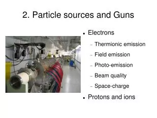
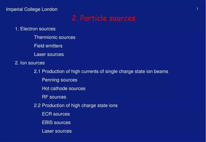
2. Particle sources. 1. Electron sources Thermionic sources Field emitters Laser sources 2. Ion sources 2.1 Production of high currents of single charge state ion beams Penning sources Hot cathode sources RF sources 2.2 Production of high charge state ions

E N D
2. Particle sources 1. Electron sources Thermionic sources Field emitters Laser sources 2. Ion sources 2.1 Production of high currents of single charge state ion beams Penning sources Hot cathode sources RF sources 2.2 Production of high charge state ions ECR sources EBIS sources Laser sources
2. Particle sources 2.3 Production of negatively charged ion beams Surface Production Volume Production 3. Extraction of particle beams 3.1 The space charge limit and Child-Langmuirs law 3.2 External and internal fields in the extractor, laminar flow and pierce angle 3.3 The beam emittance, the acceptance of the extraction system and the conservation of phase space
Electron sources Only very little energy is necessary to free electrons from the bound state or the Upper levels of the “electron gas” in solids. This can be done by : • Thermionic emission The heated electron must have an energy higher than the workfunction 2) Photoemission The photon energy must exceed the work function 3) Field emission high external electric fields alter the potential barrier, and allow electrons to be extracted by the tunneleffect
Diode characteristic Temperature limited current Space charge limited voltage Current density as a function of Binding energy and temperature Richardson-Dushman equation Material A F(eV) Temp (° K) J (A/cm2) Tungsten 60 4.54 2500 0.3 Thoriated W 3 2.63 1900 1.16 Mixed oxides 0.01 1. 1200 1. Caesium 162 1.81 Tantalum 60 3.38 2500 2.38 Cs/O/W 0.003 0.72 1000 0.35
Field emission of electrons from surfaces Fowler Nordheim : J: emission current density (A/cm2) B: field-independent constant [A/V2] E: applied field (V/cm) F0: work function (eV)
Field emission of electrons from surfaces Single carbon nano tube (CNT) and CNT arrays for the production of high brightness electron beams Field emitter arrays, designed for the production of large panel plasma screens
light free electrons photo cathode Light (l) ring anode I pA + - U U (I=0) bound electrons uv- lamp zinc-plate h glass f0 Photo effect f f
Photo effect and laser sources DESY PITZ 2 source (LC / XFEL)
Production of high currents of single charge state ion beams For efficient ion production the electron energy should be app. 2-4 times the ionization energy of the ion. The impact of electron with gaseous atoms is mostly used for the production of ion beams.
Production of high currents of single charge state ion beams A Townsend gas discharge using an avalanche effect is an very effective way to produce a high amount of ions. Therefore the Paschen criteria has to be fulfilled. To improve the gas discharge and to enhance plasma confinement magnetic fields are used.
Penning sources The Penning Ion Source or PIG source (Philips Ionization vacuum Gauge) invented by Penning in 1937 uses a a dipole field for plasma confinement . The strong magnetic dipole field gives high efficiency as electrons oscillate inside the hollow anode between the the two cathodes at each end. The Lifetime of the source limited by sputtering of the cathodes, especially for highly charged, heavy ion operation.
Magnetron sources The Magnetron ion source which was first presented by Van Voorhis in 1934 uses a solenoidal magnetic field for plasma confinement The field of ~ 0.1 T is generated with an external solenoid surrounding the ion source. The chamber wall serves as anode, while the cathode provides electrons through thermionic emission. The filament mounted parallel to the magnetic field forces the electrons to spiral. As with Penning sources the Lifetime of the source limited by sputtering of the cathodes, especially for highly charged, heavy ion operation.
Hot cathode sources Filament Ion Source Discharge in the plasma chamber is driven by the electrons delivered by the filament. single charged ions up to 100 mA • Plasma enclosure by magnets. • Pressure range 10-1 - 10-3 mbar. • Discharge voltage 20 - 200 V (depending on ionization voltage) • Discharge current 10 - 500 A
RF sources Non resonant excitation of plasma by RF. Only lower charge states available (low electron energy) but high beam currents possible. Internal antenna to feed RF power into plasma => limited lifetime of antenna due to sputtering, strong coupling of RF into plasma and good plasma confinement.
RF sources Production of large ion currents (I>1 A) of single charged ions for surface treatment or plasma heating (tokamaks). Multiaperture extraction therefore difficult to feed beam into conventional accelerator structure. External antenna to feed RF power into plasma => Long lifetime of antenna, but chamber has to be of non conducting material.
Production of high charge state ions The PLASMA created is increased in density by electron bombardment. The maximum charge state that will be obtained depends on the incident electron energy. e + X = X+ + 2e For multi-charge states e + X i+ = X (i+1)+ + 2e higher electron energies are required since electrons have to be removed from inner shells. The maximum charge state is limited by the incident electron energy.
ElectronCyclotronResonance Source whf = wcyc = (e/m) × B Radial and axial magnetic field distribution for the confinement of the source plasma. Only at the centre of the source the cyclotron condition for the electrons is full filled. (0.1-1 kW) Extracted ion currents for different charge states of Argon
ElectronCyclotronResonance source By variation of the longitudinal enclosing magnetic mirror configuration the charge distribution can be influenced. Schematic layout of an ECR source for the production of radioactive ion beams
ElectronBeamIonSource CRYogenic Stockholm Ion Source 17 cm Upper: First EBIS IEL-1 build by Donets in 1968, lower : Evolution of charge state distribution of nitrogen ions at Ee=5.45 keV Parameters of CRYSIS
ElectronBeamIonSource Total ion charge trapped in an EBIS as a function of confinement time, for different electron beam currents Comparison of the extractable (electric) current between ECR and EBIS. Ion current extracted from an EBIS as a function of the charge state for Na ions (Ne gas was added)
Laser Ion Sources Schematic drawing of the experimental set up of a laser ion source. By the impact of the laser with the target, a plasma is created which expands in the drift chamber and then is accelerated in the extraction gap.
LaserIon Sources By interaction of the plasma electrons with the electric field of the laser pulse the electrons are heated. This leads to a shift of the charge state distribution of the plasma ions towards higher charge states. The different charge states of the plasma are separated by the drift longitudinally and reduce space charge in the acceleration gap
LaserIon Sources The different charge states of the plasma are separated by the drift longitudinally (higher charge states first) and reduce space charge in the acceleration gap. The available laser power density on the target (for fixed total laser power influenced by beam size on target) strongly influences the charge state distribution of the plasma
g Production of negatively charged ion beams Conserving energy when forming a negative ion through direct electron attachment, the excess energy has to be dissipated through a photon. A + e = A¯ + g. But radiative Capture is rare (5•10-22cm2for H2). Three Types of H- Ion Sources are in use • Surface conversion sources • Volume production sources • Hybrid production sources Higher cross sections (~10-20cm2 for H2and Ee>10 eV) can be realized when the excess energy can be transferred to a third particle, M + e = A + B + e and sometimes = A + B¯ Even better are processes which excite a molecule to the edge of breakup (vibrationally excited 4<n<12) and then dissociated by a slow electron Cs can be used as an electron donator, but the ionisation energy of 3.9 eV is much higher than the 0.75 eV electron affinity of H- => Surface treatment
Production of negatively charged ion beams Magnetic dipole fields can be used as filters to create areas of different electron temperatures Cross sections for different production and destruction mechanisms
Sources using surface production Picture of the LANCE surface source Schematic layout of the LANCE surface source using a filament driven gas discharge for plasma production and surface conversion on a Cs target for H- formation
Sources using volume production The small experimental H- source in Frankfurt used a hot cathode driven gas discharge, dipole fields and a Pt surface cover for the reduction of the dissociation of the H2 molecules
Sources using hybrid production schemes The RAL H- source uses a Penning discharge (dipole for plasma production and to influence electron temperature) and Cs injection. The SNS H- source developed in Berkley uses RF to produce the plasma, dipoles to influence the electron density and a Cs collar.
External and internal fields in the extractor, laminar flow and pierce angle
External and internal fields in the extractor, laminar flow and pierce angle
The beam emittance, the acceptance of the extraction system and the conservation of the phase space
The beam emittance, the acceptance of the extraction system and the conservation of the phase space
The beam emittance, the acceptance of the extraction system and the conservation of the phase space