Download
1 / 1
10 likes | 78 Views
2.875”. 1”. 1”. 10.75”. 10.25”. 11”. U-Beam. .125”D Rivet Holes. .75”. .125”. 2.375”. 1.375”. Bridging the Paper River Chasm. B. Hart E. Konicki M. Brown. ME 104Q. Team “No Idea”. Executive Summary

E N D
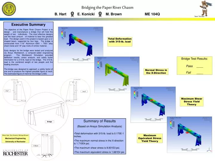
2.875” 1” 1” 10.75” 10.25” 11” U-Beam .125”D Rivet Holes .75” .125” 2.375” 1.375” Bridging the Paper River Chasm B. Hart E. Konicki M. Brown ME 104Q Team “No Idea” Executive Summary The objective of the Paper River Chasm Project is to design and manufacture a bridge that will hold the weight of two individuals. The most effective designs use the least amount of material to bear the greatest load. The design used in this project is based upon a U-shaped beam, supported by four legs. The bridge is constructed from 1/16” Aluminum 6061 – T651 alloy sheet metal and 1/8” pop rivets of similar material. Early designs for the bridge were tested and analyzed via Ansys Workbench, a computer-aided engineering program. The Workbench Simulation provided deflection results, stress analysis, and safety factor information for a 315-lb. load on the bridge. The 315-lb. load is the combined weight of two people and the loading structure. The bridge was designed to approach a safety factor of one and to produce the highest possible figure of merit. The estimated figure of merit for the bridge is 805. Total Deformation with 315-lb. load Bridge Test Results: Pass____ Fail ____ Normal Stress in the X-Direction .125” D Rivet Hole .125” D Rivet Hole 4.125” Leg 1 4.125” Leg 2 3.875” 3.875” 3.375” 3.375” Maximum Shear Stress Yield Theory 1” 1” 2” 2” • Summary of Results • (Based on Ansys Simulation Analysis) • Total deformation with 315-lb. load is 0.175E-1 inches. • The maximum normal stress in the X-direction is 1.710E4 psi. • The maximum shear stress is 8.831E3 psi. • The maximum equivalent stress is 1.681E4 psi. Bridge Maximum Equivalent Stress Yield Theory Brian Hart, Eric Konicki, Michael Brown Mechanical Engineering University of Rochester