Download
1 / 10
140 likes | 884 Views
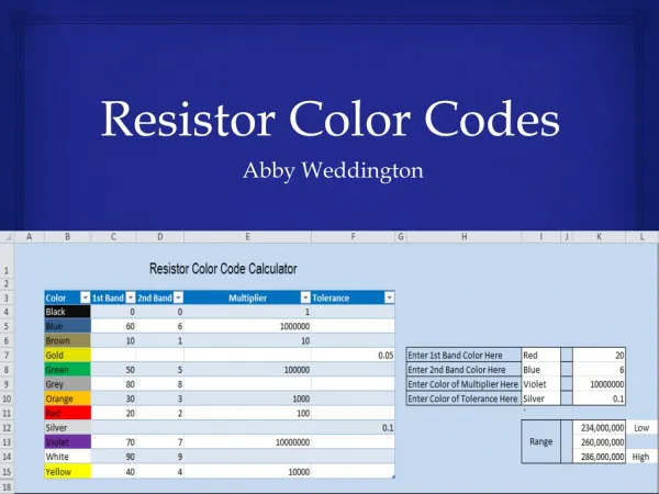
5.2a Poly Resistor. Value of resistor is from Problem 5.1=1K Ω Sheet resistance of poly=25Ω/ Thus number of squares in poly resistor=1KΩ/25Ω/ =40 Therefore L/W=40. Minimum feature size (2 l )=2 m m

E N D
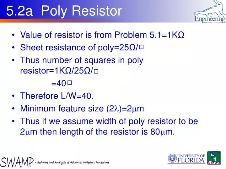
5.2a Poly Resistor • Value of resistor is from Problem 5.1=1KΩ • Sheet resistance of poly=25Ω/ • Thus number of squares in poly resistor=1KΩ/25Ω/ =40 • Therefore L/W=40. • Minimum feature size (2l)=2mm • Thus if we assume width of poly resistor to be 2mm then length of the resistor is 80mm.
Steps in Layout of Resistor • Since the minimum dimension in question 5.2 is 2mm. Therefore we should use the technology file corresponding to l=1mm
Resistor Layout There are 5 long sections of length 17l and width 2l Thus the number of squares is (5x17)/2~42 Also the edges contribute another 4 squares There is additional resistance due to current crowding at the corners and also the poly contact regions add additional resistance.
W/L of nfet was 90 • Since L is 2l=2mm, W=180mm (90x2l) • Remember to account for Ld (lateral diffusion) in L of NMOS
Extraction • Once layout is drawn, DRC cleared and saved, it is ready to be extracted • Go to tools and click on extract • The window shown will appear. In the definition file tab, choose the appropriate technology file from the folder it is present by browsing. • Then hit run, the extracted output file can be opened with notepad.
Extracted file The extracted file will look as such This is the information required from extracted file to be used in spice Note: L=2.5mm to account for lateral diffusion mentioned in q.5.2
Pspice • First draw the circuit. Choose MbreakN part and place it. • Goto edit and click on model • Choose the Edit instance model (text) • Add the model parameters as below and click ok .model NMOD NMOS ( LEVEL=1, VTO=1 GAMMA=0.2 KP=20U) *$ • Also double click on part and change the attributes according to extracted Ledit file • Other parameters and other level models can also be added for more complex simulations • Finish the circuit by adding the dc source
Analysis • Choose dc sweep analysis • Click on the this tab and choose the voltage source to be swept and its range • Here the input voltage name is V3 and it was initialized to 0V
VIL,VIH determination The blue curve represents dVout/dVin, the markers point to where the slope is -1 VIL=1.5V, VIH=3.09V