Download
1 / 28
300 likes | 597 Views
FABRICATION PROCESSES. Presentation on ‘FABRICATION PROCESSES’. Course no : EEE 453 Course by : Mohiuddin Munna. Presented by Shahadat Hussain Parvez (2010338004) Jubair Hossain Jitu (2010338006) Rezwan Matin (2010338015) Gurucharan Mahato (2010338037).

E N D
FABRICATION PROCESSES Presentation on ‘FABRICATION PROCESSES’ Course no : EEE 453 Course by : MohiuddinMunna Presented by Shahadat Hussain Parvez (2010338004) JubairHossainJitu (2010338006) RezwanMatin (2010338015) GurucharanMahato (2010338037)
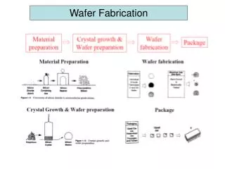
Before Starting the Fabrication It starts with making silicon
Before Starting the Fabrication • Ingots get cut into wafers, which are 1-2mm thick, and upto 12” in diameter • Entire wafers are processed, and then cut into chips when needed
Fabrication Processes Six main process steps • Oxidation • Diffusion • Ion implantation • Lithography • Thin film deposition • Epitaxy
Oxidation • the first step in semiconductor device fabrication involves the oxidation of the wafer surface in order to grow a thin layer of silicon dioxide (SiO2). This oxide is used to provide insulating and passivation layers. • The most common method of oxidation is thermal, and can be classified as either "dry" or "wet" oxidation. Wafers are loaded into quartz boats and slid into a furnace heated to approximately 1200ºC.
Oxidation • In dry oxidation, thin oxide layers are grown in an environment containing oxygen and hydrogen chloride near atmospheric pressure
Oxidation • Thicker oxide layers require higher pressures and the use of steam (wet oxidation). Wet oxidation is performed by exposing the wafer to a mixture of oxygen and hydrogen in the furnace chamber. Water vapor is formed when the hydrogen and oxygen react
Oxidation Process • Standard oxidation temperature 800-1200 C • Heat is produced by resistance heating • Coil like heating elements are arranged in 3 controlled zone • Outer zones operates at higher power to compensate heat loss • Simply Oxygen is fed for dry oxidation • Carrier gas like Ar on N2 is used in wet oxidation along with heated water or burning O2 and H2 at input of tube • Required time in furnace depends on temperature and desired thickness • Whole system is automated
Oxidation Process Fig: Typical Thickness Vs Oxidation time for 100 crystal compared for dry and wet oxidation
Diffusion process • Process of doping • Si wafer is exposed to solid, liquid or gaseous source containing desired impurity • A reaction at wafer surface establishes a supply of dopant atoms immediately adjacent to Si crystal • At elevated temperature atoms difuse in the region Si is not protected by oxide • Surface doping concentration is up to 1021 / cm3 • Diffusion in SiO2 is relatively low • SiO2 protects Si for a limited time depending on oxide thickness ,temperature and background droping.
Ion Implantation • It’s an alternative process of introducing dopants • Dopant ion is accelerated in high energy range from 5 keV to 1MeV then shooted into semiconductor • Ions displace Si atoms along their path into crystal • follow-up heating binds ions with crystel • But before that automatic scanning is performed automatically to determine total number of ions / cm3 • Si wafer can be masked using thin flims of SiO2 ,Si3N4 and photoresist .
Advantage of Ion Implantation • Lower temperature process • Implantation is performed in room temperature • Follow-up heating is done in 600 C • Gives precise control over impurity • Ideally suited for a number of modern device structures requiring extremely shallow junctions • damage from implantation can be annealed by heating the wafer in a furnace to T > 900 C.
Doping by Ion Implantation • Dose = ion beam flux (# cm-2 s-1) x time for implant ... units # cm-2
Doping by Ion Implantation • SiO2 film masks the implant by preventing ions from reaching the underlying silicon (assuming it’s thick enough) • after implantation, the phosphorus ions are confined to a damaged region near the silicon surface
Doping by Ion Implantation • Annealing heals damage and also redistributes the ions (they diffuse further into the silicon crystal)
Doping by Ion Implantation Fig: Computed phosphorus Implantation profile assuming a constant dose of 1014 /cm
Lithography • Process of selectively removing SiO2 and other masking material covering wafer surface. • Transfers circuit diagram on wafer
Lithography Process • At first Si wafer is coated with UV light sensitive photoresist in a thin uniform coating. • Wafer is pre baked at 80-100 C • Exposing wafer to UV light through a mask • Mask here is carefully prepared with glass or quartz photo pale containing a copy of pattern to be transferred to SiO2 • Exposed photoresist parts undergo chemical changes depending on photo resist • In negative photo resist exposed parts form polymer like structures and unexposed parts dissolves after developing
Lithography Fig: majos steps in lithography Apply resist Expose resist through mask After developing After oxide etching and resist removal
Thin Film deposition Three different Techniques • Evaporation • Sputtering • Chemical Vapor deposition
Chemical Vapor Deposition(CVD) • 1.Atmospheric Pressure CVD • 2.Low Pressure CVD • 3.Plasma Enhanced CVD
Epitaxy Epitaxy is a special type of thin layer deposition. • Whereas deposition described in the previous yields either amorphous or polycrystalline layer, it yield a crystalline layer