Download
1 / 39
410 likes | 516 Views
PFOS USE IN THE SEMICONDUCTOR INDUSTRY LRTAP Review Process. June 2005. Addition of Chemicals to LRTAP – Information Elements. Executive Body Decision 1998/2, Paragraph 1 lays out information required for evaluating proposed additions Data elements include: Production/uses/emissions…

E N D
PFOS USE IN THE SEMICONDUCTOR INDUSTRY LRTAP Review Process June 2005
Addition of Chemicals to LRTAP –Information Elements • Executive Body Decision 1998/2, Paragraph 1 lays out information required for evaluating proposed additions • Data elements include: • Production/uses/emissions… • Socio-economic factors, including: • Alternatives and their efficacy • Known adverse environmental or health effects of alternatives • Process changes, controls, prevention techniques which can reduce emissions of the substance
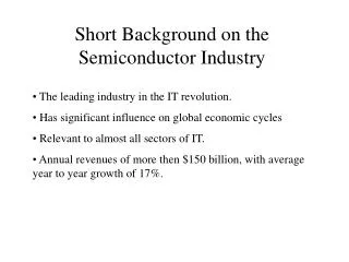
Key Messages • Semiconductor sector is a strategic industry – enables economic productivity growth, sustainable development, etc. • PFOS is used in very small quantities in s/c photolithography, playing a critical role in several applications – no current substitutes • PFOS carefully managed in s/c manufacturing to yield de minimis emissions and exposure • This fact recognized by EU SCHER Committee and US EPA • Semiconductor industry committed to finding substitutes for current critical uses of PFOS • No “drop-in” or “one-size-fits-all” substitutes available; substitution process will take time and millions of Dollars/Euros of research • Most likely PFOS alternatives are PFASs; they are not PBTs
Presentation Outline • Background • Overview of semiconductor industry • Semiconductors and the economy • PFOS definitions • Production/uses/emissions • Basic steps in semiconductor manufacturing • The semiconductor technology development cycle • How and why semiconductors used in photolithography • PFOS carefully managed in photolithography • US regulatory action on PFOS • EU SCHER report conclusions re PFOS in semiconductor industry
Presentation Outline • Alternatives • Critical vs. Non-critical • The PFOS substitution process • Progress in eliminating “non-critical” PFOS uses • Known health effects of alternatives • Industry Voluntary Commitment
Research National Security Banking systems Services Leisure Informatic Communications Medical systems Education Microelectronic Electronic Transportation Industry Environment Semiconductors at the Heart of the Modern Economy
Overview of the Semiconductor Industry • Value Added • Semiconductor companies • $213 billion worldwide sales in 2004 • SEMI • $28 billion worldwide chemicals/materials sales in 2004 • Jobs created in semiconductor industry • 226,000 in US • 80,000 in EU • Semiconductor industry at the heart of recent productivity growth gains in US economy
Semiconductors and the Economy “A consensus has emerged that the development and deployment of information technology (IT) is the foundation of the American growth resurgence. The mantra of the ‘new economy’ – faster, better, cheaper – characterizes the speed of technological change and product improvement in semiconductors, the key enabling technology.” Source: Harvard Economics Professor Dale Jorgenson, 2005 Semiconductor Industry Association Annual Report (Emphasis added)
Semiconductors and the Economy "Semiconductors are for the Information Society, what grain was for the agrarian society and iron and steel were for the industrial society." Source: Adapted from the Shanghai Museum for Urban Development 2004
Definitions Lower MW PFAS Homologues Higher MW PFAS Homologues • PFAS is…. • PFOS is… PFOS Chemical Structure C1 –C4 C5 – C7 C8 C9 – Cn PFOS MW = Molecular Weight
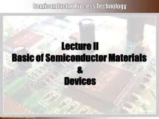
Oxidation Basic Steps in Semiconductor Manufacturing Photolithography Doping (Ion Implantation/diffusion) 15-30 Iterations Thin Film Deposition Etching Metallization CMP
Exhaust routed to appropriate air pollution control device Resist applied via Spin Coating Process may or may not be utilized Lithography Process Steps Effluents Typical Photolithography Process Life Cycle Typical Photolithography ProcessLife Cycle BARC applied via Spin Coating EBR/RER applied via Spin Coating TARC applied Pre-expose Bake Expose Post-expose Bake Develop Polyimides BARC, Resist Wastes and EBR/RER To Solvent Waste Tank Disposed via Fuel Blend/Incineration Developer and TARC Wastes to IW Drain
The Semiconductor TechnologyDevelopment Cycle • The semiconductor manufacturing process is highly complex • As circuit features get ever smaller, specialty chemicals like PFOS become ever more important • Chemicals and materials must work precisely with advanced equipment (“tools”) to accomplish high-yield, high-volume manufacturing • The process for developing new chemicals, new tools, and ensuring that the two work together in a manufacturing environment can take 10-15 years to complete • Substitution of new materials into an existing process cannot happen quickly
Integration Mfg. Ramp Demonstration Fundamental Research The Semiconductor TechnologyDevelopment Cycle Too close for change Supplier R&D Toxicity Evaluation 8 6 2 0 10 4 Years Ramp to High Volume Manufacturing
How PFOS is Used in Photolithography • Photoacid Generators (PAGs) • Anti-Reflective Coatings (ARCs) • Top Anti-Reflective Coatings (TARCs) • Bottom Anti-Reflective Coatings (BARCs) • PFOS-based Surfactants
Why is PFOS in Photoacid Generators? • Photoacid Generators (PAGs) • Photoresists for 248nm and shorter wavelengths rely on chemical amplification • During exposure the photoacid generator forms an acid catalyst which aids in creating the desired image • PAGs control diffussion which results in better resolved features and smaller scale roughness • Reduced roughness translates into reduced risk of semiconductor failure during critical applications • Photo-acid generators used for this purpose are typically sulfonic acids • PFOS is currently the ONLY chemical that can provide the necessary acidity
Light Source Mask Mask * * * * Resist * * * Resist * * * * * * * * * * * * * * Substrate Photoacid Generator Example PAGs give a 2:1 resistpolymer chain destructionfor each photon of light - CHEMICAL AMPLIFICATION
Photoacid Diffusion Control 65 nm Short Diffusion Long Diffusion Path of catalyst Resist morphology Feature Foot Well resolved features Smaller scale roughness(exemplary of PFOS PAG) Poorly resolved features Larger scale roughness(exemplary of non-PFOS PAG) Feature roughness can cause failure in critical applications
Why is PFOS in ARCs and Surfactants? • Anti-Reflective Coatings (ARCs) • Refractive index (RI) must be as close as possible to the square root of the photoresist RI • Only fluorinated materials can meet this requirement • PFOS-based Surfactants • Surface tension can produce thickness variations that emanate from the wafer center during spin-on photoresist application • PFOS-based surfactants are particularly effective in: • Lowering the surface tension • Reducing thickness variation • Creating more uniform films
Light Source Mask Mask Resist Resist Metal Substrate Light Source Mask Mask Resist Resist ARC ARC Metal Substrate Anti-Reflective Coating Example Metal substrates can reflect photons back from the surface – into areas of the resist not to be exposed. ARCs absorb the photons and prevent them from reflecting back – the composition and capabilities of the ARC must be matched to the resist and the light source.
PFOS Carefully Managed inSemiconductor Manufacturing • Small quantities of PFOS in “critical” applications • PFOS stringently managed in photolithography process to minimize emissions and exposure • End result: de minimis emissions and exposure *Data Source: ESIA-SEMI 2002 PFOS Mass Balance
Photolithography Equipment Coater Bowl Coater Bowl Cabinet
Semiconductor IndustryPFOS Use in Perspective – EU Case Data source: RPA/BRE RRS August 2004
ResistChemical DeveloperChemical DryStrip PFOSDestroyed Cleans Photo Develop WetStrip Trash (solid) Wastewater In SomeCountries Incineration Air Processing Steps PFOS Waste Sinks Generic Semiconductor PFOS Mass Balance Flow Diagram
ESIA-SEMI PFOS Mass Balance Example 2002 Summary • Total PFOS incinerated 196.5 kg • Total PFOS released to wastewater 238.4 kg • Total amount of PFOS used annually 435.9 kg • % of PFOS incinerated 45% Example in event of no PFOS use in developer: • PFOS in EBR 85.3 kg • PFOS in photoresist PAG & Surfactant 44.9 kg • PFOS in TARC 104.1 kg • PFOS in BARC 6.6 kg • Total amount of PFOS used annually 240.9 kg • Total estimated PFOS released to wastewater 43.38 kg • % PFOS incinerated 82%
US Regulatory Action on PFOS • Following 3M action phasing out their PFOS products, USEPA issued rule essentially banning future uses of PFOS without new chemical approval • USEPA provided for three limited exemptions from the ban, including one for critical photolithography uses in the semiconductor industry – photoresists, ARCs, and surfactants • Exemption was based on showing by industry that: • These chemicals are critical to semiconductor manufacturing • Their use in semiconductor manufacturing is tightly controlled • Releases to the environment are de minimis
EU SCHER Conclusions onSemiconductor PFOS Use • Scientific Committee on Health and Environment (SCHER) advises EU Commission on chemical risk management issues • Recent review of PFOS uses in Europe concluded: “The contribution of the confirmed on-going industrial/professional uses to the overall risks for the environment and for the general public are probably negligible with regard to the sectors…[including] semiconductor industry…” Source: SCHER report, February 2005 (Emphasis added)
“Critical” vs. “Non-Critical” PFOS Uses • The distinction between “critical” and “non-critical” revolves around the availability, or expected availability, of technically-adequate substitutes where PFOS makes a unique contribution to the manufacturing process • The semiconductor industry has eliminated non-critical uses, substituting other chemicals that can serve the same purpose • Remaining PFOS uses are those for which there are no readily available substitutes (e.g., PAGs and ARCs) . • Finding substitutes for all critical PFOS uses will take many years of research and qualification in high-volume manufacturing • Among the issues to be faced • Highly competitive industry; • Confidentiality issues; • Information not readily available; and • Because of low volumes, supplier interest is mixed
The PFOS Substitution Process • Considerable engineering required to make the PFOS-free alternatives work in manufacturing • A semiconductor manufacturing is a combination of 100-400 steps that are all partly dependent on each other • Each technology is unique • Any or all of the steps may be different, as well as their processing parameters (e.g. feature size) • A photolithography step in one technology is not equivalent to another technology, although sometimes they are similar • Introducing a new resist requires an extensive qualification for each technology use • Up to 20 different resist uses could exist in one technology • This qualification is costly and involves many engineers • Development engineers working primarily on legacy resists cannot work on the newest technologies • Total technology development timeline impacted PFOS alternatives are not “drop-in” replacements
Semiconductor Industry Progress inEliminating “Non-Critical” PFOS Uses • Developers: • Industry is in the process of phasing out PFOS-containing developers because alternatives exist with same performance • Etchants: • Alternatives with same performance exist and are used • Emission controls: • PFOS containing solvent waste from semiconductor manufacturing is incinerated at high temperatures • Wastewater treatment: • Wastewater point of use abatement technology under evaluation (ISMT); Concentration in ng/l ALARA principle
Semiconductor Industry Progress inEliminating “Non-Critical” PFOS Uses • PFOS Consumption: • Total use of PFOS continues to decline as the industry goes from 200 mm to 300 mm wafer size • Wafer area increases 125% • Amount of resist used drops from 3 ml to 1 ml per wafer 85 % less resist used on a per wafer basis • Voluntary Commitment: • Industry is working on an INTERNATIONALvoluntary approach to reduce emissions from PFOS use because the semiconductor manufacturing industry is truly a global industry
Known Health Effects of Alternatives • Lower homologues of Perfluoroalkyl sulfonates (PFAS) are thought be the most likely replacements for PFOS • Currently these are the only known potential alternatives • Effectiveness is unknown • Studies* suggest that lower homologues of PFASs are not PBTs • Low bioaccumulation factor (<1) • Lower environmental persistence • Nearly non-toxic to mammals • Not acutely eco-toxic * See 3M’s information at: http://multimedia.mmm.com/mws/mediawebserver.dyn?TTTTTTB_LdgTmwUTfwUTTTj7zDsssssr
Industry Voluntary Commitment • Voluntary Commitment being developed by World Semiconductor Council member associations (SIA, ESIA, JSIA, etc.) • Proposed elements include: • Stop non-critical uses • Incineration of solvents containing PFOS • Equipment effluent optimization research • Work towards critical use phase-out • Research for alternatives to perfluorinated chemistry • Wastewater effluent evaluations of control technology • Reporting activity