Download
1 / 22
220 likes | 382 Views
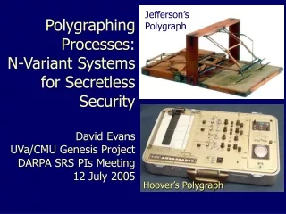
A Two-Input Polygraph. Archana Venkataraman Christopher Buenrostro Isaac Rosmarin. Outline. Introduction Design Overview The Physiological Sensors The Digital Decision-Making Unit (DDMU) The Output Display Conclusion. Introduction.

E N D
A Two-Input Polygraph Archana Venkataraman Christopher Buenrostro Isaac Rosmarin
Outline • Introduction • Design Overview • The Physiological Sensors • The Digital Decision-Making Unit (DDMU) • The Output Display • Conclusion
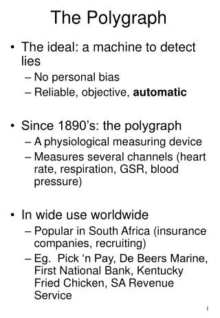
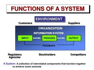
Introduction • The polygraph detects stress-related physiological responses commonly linked with deception • Modern-day polygraphs rely on 4 major variables: • The Foundation of a lie-detector examination is in its structure • Environmental Setting • Experience and Conduct of Examinator • Questions: Control, Irrelevant, and Relevant • Decisions are based on the assumption that an innocent subject will react more strongly to the control questions and a guilty subject will react more strongly to the relevant questions
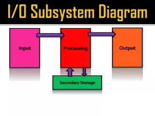
Introduction • The project uses 2 inputs to make decision– heart rate and skin conductivity • Heart speeds up during times of emotional stress • Perspire during times of emotional stress – increases conductivity • Project divided into three sections • The Physiological Sensors • The Digital Decision-Making Unit • The Output Display
Input Devices Inputs DDMU Video Data Acquisition Flow Diagram Probe Patches Attached to Test Subject Heart Rate Monitor Analog-to-Digital Converter Designated Lab Kit RAM Refresh Block Probe Patches Attached to Test Subject Skin Conductivity Monitor Analog-to-Digital Converter
Input Devices Inputs DDMU Video Data Acquisition Flow Diagram Probe Patches Attached to Test Subject Heart Rate Monitor Analog-to-Digital Converter Designated Lab Kit RAM Refresh Block Probe Patches Attached to Test Subject Skin Conductivity Monitor Analog-to-Digital Converter Not Sync'd to System...
Input Devices Inputs DDMU Video Data Acquisition Flow Diagram Probe Patches Attached to Test Subject Heart Rate Monitor Analog-to-Digital Converter Designated Lab Kit RAM Refresh Block Probe Patches Attached to Test Subject Skin Conductivity Monitor Analog-to-Digital Converter Also Not Sync'd to System...
Input Devices Inputs DDMU Video Data Acquisition Flow Diagram Sync'd to System! Probe Patches Attached to Test Subject Heart Rate Monitor Analog-to-Digital Converter Designated Lab Kit RAM Refresh Block Probe Patches Attached to Test Subject Skin Conductivity Monitor Analog-to-Digital Converter
Input Devices Inputs DDMU Video Data Acquisition Flow Diagram Probe Patches Attached to Test Subject Heart Rate Monitor Analog-to-Digital Converter Designated Lab Kit RAM Refresh Block Probe Patches Attached to Test Subject Skin Conductivity Monitor Analog-to-Digital Converter Digital Signals (27MHz Clock) Continuous Signals
Input Devices Inputs DDMU Video Data Acquisition Flow Diagram Probe Patches Attached to Test Subject Heart Rate Monitor Analog-to-Digital Converter Designated Lab Kit RAM Refresh Block Probe Patches Attached to Test Subject Skin Conductivity Monitor Analog-to-Digital Converter Bottleneck to Speed of Entire System!!!
Electrocardiogram Heart Monitor Inputs DDMU Video Ramsey Electronics ECG1C *Images from http://ramseyelectronics.com
Skin Conductivity Monitor Inputs DDMU Video The Galvactivator *Images from http://vismod.media.mit.edu/tech-reports/TR-542.pdf with credit to Rosalind W. Picard and Jocelyn Scheirer
To Memory Interface Module To Memory Interface Module Memory Module User Commands Capture Decision-Making Algorithm User Inputs Data Register Display Driver Screen Capture Commands Data to Be Displayed on Screen The Digital Decision-Making Unit Inputs DDMU Video Design Overview • User Interface • Decision-Making Portion Based on Polygraph Data • Additional Functions • Obtain Data Stored Externally in RAM • Prepare/Send Data to Display Unit
To Memory Interface Module To Memory Interface Module Memory Module User Commands Capture Decision-Making Algorithm User Inputs Data Register Display Driver Screen Capture Commands Data to Be Displayed on Screen Capturing User Commands Inputs DDMU Video • Module registers all user inputs and passes them to appropriate module • User Commands: • Type of Question • Analyze Results • Display Data • Store Data • Screen Capture
To Memory Interface Module To Memory Interface Module Memory Module User Commands Capture Decision-Making Algorithm User Inputs Data Register Display Driver Screen Capture Commands Data to Be Displayed on Screen Decision-Making Algorithms Inputs DDMU Video • Main Module of the DDMU – Analyzes sensor data and outputs binary “TRUTH/LIE” decision • Digital Pre-Processing on data to remove extraneous, environmental factors • Average incoming data • Highpass Filter • Implement one or more of following algorithms: • Compare statistics of time signal • Convert to frequency domain and compare • Hypothesis Testing
To Memory Interface Module To Memory Interface Module Memory Module User Commands Capture Decision-Making Algorithm User Inputs Data Register Display Driver Screen Capture Commands Data to Be Displayed on Screen The Memory Module and Data Register Inputs DDMU Video • The Memory Module signals Memory Interface to Read from and Write to RAM by asserting a “request” signal • Data Register holds critical values for the Decision-Making Algorithm: • Time sequences to be compared • Computed Statistics
To Memory Interface Module To Memory Interface Module Memory Module User Commands Capture Decision-Making Algorithm User Inputs Data Register Display Driver Screen Capture Commands Data to Be Displayed on Screen Display Driver Inputs DDMU Video • Gathers data to be sent to Display Unit • Sensor Data • Decision (T/F) • Screen Capture Command
Video Display Inputs DDMU Video Job of the Video Display • Take in data and convert to a visually appealing format • Display data • Save previous data for reference
Video Output Inputs DDMU Video • On computer monitor • Like PS3/Lab 4 • Higher Resolution
Data Inputs Inputs DDMU Video • Register data on vsync refresh • Convert data into an eye-pleasing format
Video Storage Inputs DDMU Video • Compresses data to save • Displays previous data • Interacts with onboard RAM • Changes based on user input
Conclusion • Design is modular • Project is good extension to material presented in class • Polygraph is an interesting real-world application