Download
1 / 1
10 likes | 101 Views
Most of the failures were tracked down to anomalous trigger conditions during data taking. Trigger TORTURE tests (to explore dead-time at high trigger rates) Fake triggers generated according to the fixed beam structure. Synchronous!.

E N D
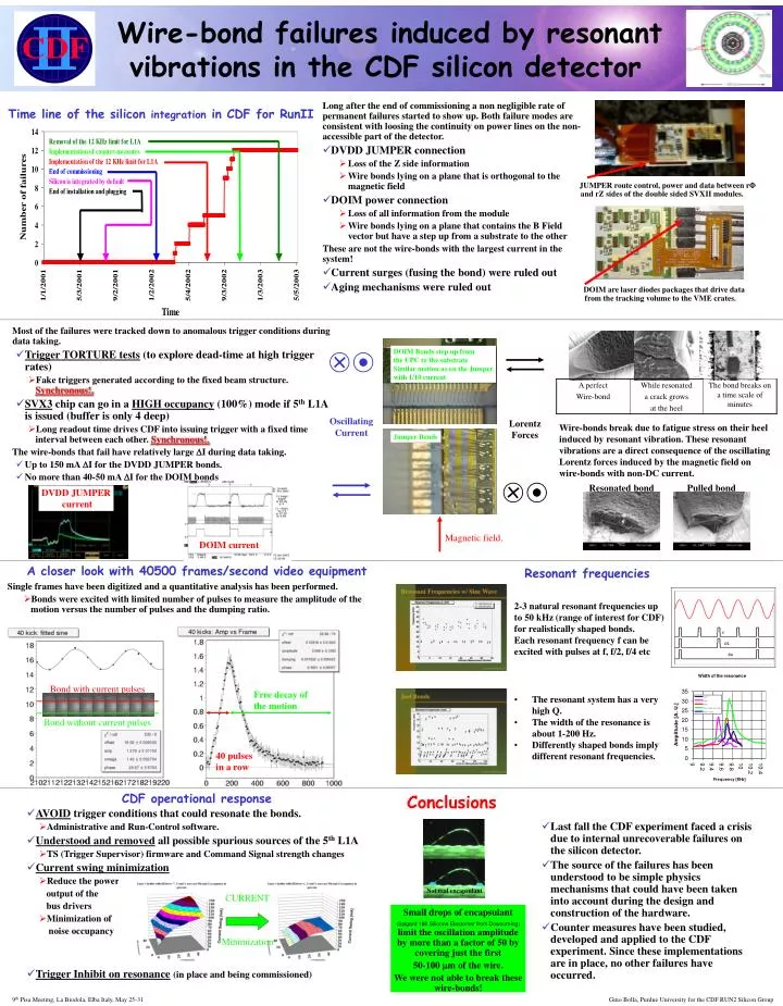
Most of the failures were tracked down to anomalous trigger conditions during data taking. • Trigger TORTURE tests (to explore dead-time at high trigger rates) • Fake triggers generated according to the fixed beam structure. Synchronous!. • SVX3 chip can go in a HIGH occupancy (100%) mode if 5th L1A is issued (buffer is only 4 deep) • Long readout time drives CDF into issuing trigger with a fixed time interval between each other. Synchronous!. The wire-bonds that fail have relatively large DI during data taking. • Up to 150 mA DI for the DVDD JUMPER bonds. • No more than 40-50 mA DI for the DOIM bonds DOIM Bonds step up from the CPC to the substrate Similar motion as on the Jumper with 1/10 current Oscillating Current Lorentz Forces Jumper Bonds DVDD JUMPER current Resonated bond Pulled bond Magnetic field. DOIM current CURRENT Minimization Wire-bond failures induced by resonant vibrations in the CDF silicon detector • Long after the end of commissioning a non negligible rate of permanent failures started to show up. Both failure modes are consistent with loosing the continuity on power lines on the non-accessible part of the detector. • DVDD JUMPER connection • Loss of the Z side information • Wire bonds lying on a plane that is orthogonal to the magnetic field • DOIM power connection • Loss of all information from the module • Wire bonds lying on a plane that contains the B Field vector but have a step up from a substrate to the other These are not the wire-bonds with the largest current in the system! • Current surges (fusing the bond) were ruled out • Aging mechanisms were ruled out Time line of the silicon integration in CDF for RunII JUMPER route control, power and data between rF and rZ sides of the double sided SVXII modules. DOIM are laser diodes packages that drive data from the tracking volume to the VME crates. Wire-bonds break due to fatigue stress on their heel induced by resonant vibration. These resonant vibrations are a direct consequence of the oscillating Lorentz forces induced by the magnetic field on wire-bonds with non-DC current. A closer look with 40500 frames/second video equipment Resonant frequencies • Single frames have been digitized and a quantitative analysis has been performed. • Bonds were excited with limited number of pulses to measure the amplitude of the motion versus the number of pulses and the dumping ratio. 2-3 natural resonant frequencies up to 50 kHz (range of interest for CDF) for realistically shaped bonds. Each resonant frequency f can be excited with pulses at f, f/2, f/4 etc Bond with current pulses Free decay of the motion • The resonant system has a very high Q. • The width of the resonance is about 1-200 Hz. • Differently shaped bonds imply different resonant frequencies. Bond without current pulses 40 pulses in a row Conclusions CDF operational response • AVOID trigger conditions that could resonate the bonds. • Administrative and Run-Control software. • Understood and removed all possible spurious sources of the 5th L1A • TS (Trigger Supervisor) firmware and Command Signal strength changes • Current swing minimization • Reduce the power output of the bus drivers • Minimization of noise occupancy • Trigger Inhibit on resonance(in place and being commissioned) • Last fall the CDF experiment faced a crisis due to internal unrecoverable failures on the silicon detector. • The source of the failures has been understood to be simple physics mechanisms that could have been taken into account during the design and construction of the hardware. • Counter measures have been studied, developed and applied to the CDF experiment. Since these implementations are in place, no other failures have occurred. Not real encapsulant Small drops of encapsulant (Sylgard 186 Silicone Elastomer from Dowcorning)limit the oscillation amplitude by more than a factor of 50 by covering just the first 50-100 mm of the wire. We were not able to break these wire-bonds! 9th Pisa Meeting, La Biodola, Elba Italy, May 25-31 Gino Bolla, Purdue University for the CDF RUN2 Silicon Group