Download

1 / 24
250 likes | 379 Views
Switching with Ultrafast Magnetic Field Pulses. Ioan Tudosa. Outline. Motivation Experiments with in-plane samples Damping Anisotropy (induced by electric field) Future ideas Terahertz radiation switching Wish List. Motivation: Understanding Ultrafast Physics.

E N D
Switching with Ultrafast Magnetic Field Pulses Ioan Tudosa
Outline • Motivation • Experiments with in-plane samples • Damping • Anisotropy (induced by electric field) • Future ideas • Terahertz radiation switching • Wish List SLAC 2011
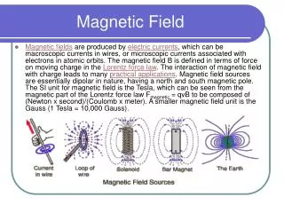
Motivation: Understanding Ultrafast Physics Basic Question: Is there any new physics to be found in exploring the fundamental limits of fast magnetization dynamics? Current work : Extremely strong electromagnetic field SLAC 2011
Experiment principle SLAC 2011 4
Experimental Set Up Long and Short Pulse Field Strengths WE HAVE PEAK FIELD VALUES OF 60 TESLA AND 20 GV/m ! Short We use two pulse lengths: Long pulse τ = 2.3*10-12 sec Short pulse τ = 70*10-15 sec Long SLAC 2011
Comparison of Field Magnitudes 60 T Magnetic Field! • Hard disk write head: 1-2 T • Superconducting magnet: 15-20 T •SLAC experiment: 60 T 20 GV/m Electric Field! • AlGaAs/GaAs quantum wells: 106 V/m • Vacuum breakdown (millitorr): 107 V/m •SLAC experiment: 2*1010 V/m SLAC 2011
Beamline setup manipulator chamber Electron bunches SLAC 2011 SLAC 2011 7
1.Sample Holder Wire scanners Samples Sample holder 1cm SLAC 2011
Precession Torques Sample is uniformly magnetized initially Maximum torque Lines of constant torque T ~ MxH ~ sin(M,H) Minimum Torque SLAC 2011
Fe/GaAs Thin Films Au 10 layers Fe 10 or 15 layers GaAs • Grown using MBE • Uniaxial in-plane anisotropy • Imaged with SEMPA 15 ML Fe 10 ML Fe M0 100 mm SLAC 2011
Precessional Magnetization Reversal 3 Step Process Final Alignment Field Pulse Kick Rotations Around Hdemag SLAC 2011
Dynamics of Magnetization Damping dissipates the energy pumped into the system circle widths SLAC 2011
Damping of Magnetic Energy Experiment Calculation (LLG+magnons) FMR damping Inset: Reduction of magnetization due to magnon scattering SLAC 2011
Experiment with ultrastrong fields Sample Composition: MgO/30nm Cr80Mo20/10nm Co70Fe30/1.5 nm Pt Imaging: SEM with Polarization Analysis Magnetism and topography electric field strength is up to 20 GV / m (2 V / Angstrom) SLAC 2011
Magneto-electronic anisotropy is strong ~ E2 1000 times stronger B-field torque E-field torque SLAC 2011
Manipulating Magnetic Anisotropy Method 1: Move Atoms ●New ATOMIC arrangement gives new axis ●True magnetocrystalline anisotropy alteration Method 2: Move Electrons ● New ELECTRONIC arrangement gives new axis ● New magneto-electric anisotropy alteration ● Need ~ fs to move electrons ● Uses spin-orbit coupling Gamble S. J. et al. - PRL, vol 102, 217201, (2009) SLAC 2011
Experiment vs simulation Simulation • Takes into account: • Increased damping near the center • Additional E-field anisotropy SLAC 2011
Topographic contrast data 2.3 Picosecond Exposure •Sample has heated to at least Tc = 1200 K in a 100 μm radius •Sample is visibly damaged at the point of beam impact 70 Femtosecond Exposure • Sample shows no evidence of heating or ablation SLAC 2011
Energy loss transfer What do we know? • The pulse will excite the electron gas • The electron gas will equilibrate with the phonon system in ~1 picosecond This means some energy from the excited electron gas will reach the phonon system DURING the picosecond pulse! What do we need to know? • How does all the other energy get out? SLAC 2011
Transition Radiation Transition Radiation a charged particle crosses a boundary ε1| ε2 Coherent Transition Radiation is emitted for λ>lbunch Bunch Electric Field Sample Response SLAC 2011
Half cycle terahertz radiation • Coherent transition radiation at λ bunch length. • Highly compressed bunches: λ 10 to 100 µm • Corresponding frequencies: 3 to 30 THz • Intense pulses with the time structure of the electron beam • When focused: • Electric fields > 1 GV/m = 0.1 V/Å • Magnetic fields > 3 T • Well above other THz sources SLAC 2011
E-202 • Explore the electric field effect • Get the time scale of beam damage • Ferromagnetic and ferroelectric samples • Expose to THz radiation outside the e-beam • Use magnetic media with Hc > 9T SLAC 2011
Wish List • Beamtime during day for better support • Predictable schedule • Better access for changing samples • Bunch length diagnostics • Less radiation background (for electronics) • Tighter focus • One shot or 0.1Hz mode SLAC 2011
Conclusion • SLAC still a useful, powerful EM pulse source • Electric field influences magnetization dynamics • Potential to direct the EM pulse and focus it • Applications to magnetic recording?? SLAC 2011