Download
1 / 37
370 likes | 377 Views
UL/ANSI/NEMA Low Voltage Circuit Breakers. Installation. Codes. Product. Inspection and. Standards and. Enforcement. Certification. (verification). Safe Products and Safe. Installations. “System” Consideration. UL Standards for LV components. UL 489: Molded Case Circuit Breakers

E N D
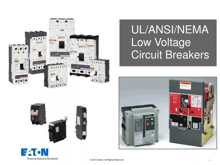
UL/ANSI/NEMA Low Voltage Circuit Breakers
Installation Codes Product Inspection and Standards and Enforcement Certification (verification) Safe Products and Safe Installations “System” Consideration
UL Standards for LV components • UL 489: Molded Case Circuit Breakers • UL 1066: LV Power Circuit Breakers • UL 98: Enclosed and Deadfront Switches • UL 508: Industrial Control Equipment
UL Standards for LV Assemblies • UL 67: Panelboards • UL 891: Switchboards • UL 1558: LV Switchgear • UL 845: Motor Control Centers • UL 857: Busway • UL 508A: Industrial Control Panels
IEC Standards for LV Components • IEC 60947: LV Switchgear and Controlgear • Part 1: General rules • Part 2: Circuit breakers • Part 3: Switches, disconnectors… • Part 4 series: Contactors and motor-starters • Part 5 series: Control circuit devices and switching elements • Part … • Part …
IEC Standards for LV Assemblies • IEC 61439: LV Switchgear and Controlgear Assemblies • Part 1: General rules • Part 2: Power Switchgear • Part 3: Distribution boards operated by ordinary persons • Part 4: Construction sites • Part 5: Distribution in public networks • Part 6: Busbar Trunking Systems (Busways) • Part 7: Marinas, camping sites, market squares, EV charging
National Electrical Code, NEC • NFPA 70, contains “installation” rules • Cable connections = AWG sizes • Wire bending spaces • Enclosure type designations • Grounding • Working spaces • Creepage/Clearance distances • Temperature rises • Mentions “Listed” products • References “product” Standards (Annex A)
UL conformity assessment • UL Listing provides • Independent confirmation of original design • On-going factory inspections • Periodic follow-up testing
Support the installed “system” UL Components IEC Components SAFE UL Assemblies IEC Assemblies
Do not “intermix” UL Components IEC Components UNSAFE UL Assemblies IEC Assemblies
System Considerations - Summary • Support your installed electrical infrastructure • Concerns extend beyond individual components • Need alignment with Installation requirements • Certification confirms initial & continued compliance • Do not intermix IEC and UL products, it will compromise safety!
Background/Evolution: LV Power Breakers UL 1066, Low-Voltage AC and DC Power Circuit Breakers Used in Enclosures
Low Voltage Circuit Breaker StandardsIEC & UL UL 1066 UL Standard for Low Voltage AC and DC Power Circuit Breakers used in Enclosures IEC 60947-2 Low Voltage Switchgear and Controlgear-Part 2 Circuit Breakers Air (Power) Circuit Breakers UL 489 UL Standard for Molded-Case Circuit Breakers Moulded Case CircuitBreakers IEC 60898 Circuit-breakers for overcurrent protection for household and similar installations
Key differences Power Circuit Breakers have compared to Molded Case Circuit Breakers • Electronic Trip Only • Used Primarily in Draw-out Switchboards • Serviceable and Maintainable • Typically used upstream from Molded Case Circuit Breakers • Provide a Higher Level of Selective Coordination • Stored Energy Mechanism
Many Standards differences between IEC 60947-2 and UL 1066, including • Testing Approach • For example, Short Circuit Interrupting Capability • Performance Requirements • For example: • Temperature Rise • Overload • Follow Up Test Requirements • For example, periodic UL 1066 Follow Up Testing
Power Circuit Breakers: Short Circuit Capability IEC 60947-2 UL 1066 References ANSI/NEMA C37.50 for: • Short-Time Current Duty Cycle • Carry fault current for two 0.5 second periods • Short-Circuit Current Duty Cycle • Single Pole Test at 87% of Interrupting Capacity (ANSI C37.50 Table 4) • Short Circuit Current Tests required in each Test Sequence (C37.50 Table 1) • Significant clause is 4.4: Utilization Categories • Category B “Determine rated short time withstand current” • Annex H Single Pole Interrupting – Optional • Ics: Rated Breaking Capacity (Seq. II) • Icu: Rated Ultimate Capability (Seq. III) UL requires defined/vigorous short circuit verifications and single pole interruption.
Power Circuit Breakers: Temperature IEC UL Maximum Allowable Temperature Rise 80°C Enclosure not required, sample previously tested in Seq. I and Seq. II 55˚C Tested in the Enclosure, tested on a new sample (C37.50 Table 1 Sequence V) Maximum allowable Temperature Rise At the Circuit Breaker Contacts No value specified but no damage to adjacent parts (Table 7 Note a) 85°C Philosophy different for temperature tests
Power Circuit Breakers: Overload Capability IEC UL Overload test requirements Required for 630A and less, optional above 630A (8.3.3.4 and Test Sequence I) Required for ALL circuit breakers (ANSI C37.50 Table 1, Seq. 1) Tests after Overload Short Circuit Test not required and not part of test sequence Short Circuit Test required UL always requires overload, also Requires short circuit test after overload
Power Circuit Breakers:Conformance Testing/Conformity Assessment IEC UL • UL Third-Party Witness of Conformance Testing • UL Factory Surveillance • UL “procedures” document the construction/components for on-going compliance • UL periodic Follow-up Testing based on production volume or number of years (ANSI C37.50 Table 7) • Conformance to IEC Standard (CE Mark) typically justified solely by manufacturer’s self declaration Third-party certification assures independent verification & ongoing conformance
Emerging technology: Addressing Arc Flash Hazards • Data is available to apply UL low voltage circuit breakers to limit arc flash energy
Traditional Circuit Protection Circuit breakers were originally intended to protect the installed conductors: • Protect & prevent possible damage for operating beyond their capability. • Cut-off current below the cable damage curves.
IEEE 1584, Guide for Performing Arc-Flash Hazard Calculations • Calculate Incident energy • Use fault current level and interruption time of the overcurrent device. • Circuit breaker calculation methods do not account for their current limiting aspects! • Published Papers referencing circuit breaker arc flash applications are: • “Molded-Case Circuit Breakers reduce Arc-Flash Hazard Impact” NEMA (available for free download from the NEMA Website) • “Understanding IEEE 1584 Arc-Flash Calculations”, K. J. Lippert, D. M. Colaberardino, and C. W. Kimblin, IEEE IAS Magazine, May/June 2005. • Applying Low Voltage Circuit Breakers to Limit Arc-Flash Energy”, G. Gregory and K. J. Lippert, IEEE PCIC, September 2006
Incident Energy at Bolted Fault Current (kA) Min Mid Max 250 A MCCB with Thermal - Magnetic Trip Unit Bolted fault current 3.7 kA 35 kA 100 kA 1 2 N/A 1.7 4.7 Inc. Energy via IEEE 1584 Table E.1 Generic (Cal/cm ) 2 27.6 0.9 1.8 Inc. Energy via IEEE 1584 & Trip Curve (Cal/cm ) 2 0.11 0.15 0.13 Measured Incident Energy ( Cal/cm ) 400 A MCCB with Thermal - Magnetic Trip Unit Bolted fault current 6 kA 35 kA 100 kA 1 2 N/A 1.7 4.7 Inc. Energy via IEEE 1584 Table E.1 Generic (Cal/cm ) 2 72 0.7 1.4 Inc. Energy via IEEE 1584 & Trip Curve (Cal/cm ) 2 0.12 0.2 0.20 Measured Incide nt Energy (Cal/cm ) 600 A MCCB with Thermal - Magnetic Trip Unit Bolted fault current 9 kA 35 kA 100 kA 1 2 N/A 2.3 5.7 Inc. Energy via IEEE 1584 Table E.1 Generic (Cal/cm ) 2 46 1.1 1.8 Inc. Energy via IEEE 1584 & Trip Curve (Cal/cm ) 2 1.22 0.78 0.36 Measured Incident Energy (Cal/cm ) 800 A MCCB with Thermal - Magnetic Trip Unit Bolted fault current 12 kA 35 kA 65 kA 1 2 N/A 2.3 3.9 Inc. Energy via IEEE 1584 Table E.1 Generic (Cal/cm ) 2 61.4 1.7 2.8 Inc. Energy via IEEE 1584 & Trip Curve (Cal/cm ) 2 0.86 1.14 1.05 Me asured Incident Energy (Cal/cm ) 1200 A MCCB with Electronic Trip Unit Bolted fault current 20 kA 35 kA 100 kA 1 2 N/A 3.5 9.4 Inc. Energy via IEEE 1584 Table E.1 Generic (Cal/cm ) 2 218 3.5 5.8 Inc. Energy via IEEE 1584 & Trip Curve (Cal/cm ) 2 1.86 1.20 1.64 Measured Incident Energy (Cal/cm ) 2500 A MCCB with Electronic Trip Unit Bolted fault current 35 kA 65 kA 100 kA 1 2 N/A 7.7 11.5 Inc. Energy via IEEE 1584 Table E.1 Generic (Cal/cm ) 2 110 5.4 6.5 Inc. Energy via IEEE 1584 & Trip Curve (Cal /cm ) 2 3.96 3.48 2.12 Measured Incident Energy (Cal/cm ) 1. N/A represents “Not Applicable” because the parameters are outside the range of the IEEE 1584 Table E.1 generic equation. Comparison of MCCB arc test results
Conclusions from Molded Case Circuit Breaker arc flash testing • In the instantaneous region, tested incident energies are significantly lower than calculated values due to: • Actual arcing time • Current reduction by the circuit breaker (particularly for current limiting circuit breakers)
Zone Selective Interlocking (ZSI) • Many modern circuit breakers have electronic trip units which make them more “intelligent” • Electronic trips with ZSI allows breakers in the same zone to communicate with each other • ZSI bypasses the preset short delay time (and ground fault delay time when available) on the upstream circuit breaker closest to the fault, which then trips with no intentional delay
When a fault occurs at point X... Main 1 Circuit Breaker X Circuit Breaker Circuit Breaker Circuit Breaker Feeder 1 Feeder 2 Feeder 3 Zone Selective Interlocking (ZSI) I sense trouble! All is OK here, so I’m quiet. All is OK here, so I’m quiet. All is OK here, so I’m quiet. Zone A Circuit Breaker Circuit Breaker
Main 1 Circuit Breaker Circuit Breaker Circuit Breaker Circuit Breaker Feeder 1 Feeder 2 Feeder 3 Zone Selective Interlocking (ZSI) But with ZSI… since none of my downstream buddies are telling me that they sense trouble, I know not to wait at all, and open as quickly as I can! Without ZSI, I’d normally wait for my Short Delay time, and then open! X Zone A Circuit Breaker Circuit Breaker
However, when a fault occurs at point XX... Main 1 Circuit Breaker Circuit Breaker Circuit Breaker Circuit Breaker Feeder 1 Feeder 2 Feeder 3 XX Zone Selective Interlocking (ZSI) I sense trouble! I sense trouble too! Hey upstream buddy, hang in there, I’ve got it! All is OK here, so I’m quiet. All is OK here, so I’m quiet. Zone A Coordination Is Maintained! Circuit Breaker Circuit Breaker
35kA fault current X Without ZSI = 0.5 S: With ZSI =0.08 S: 7.0* Cal/cm2 43.7* Cal/cm2 Cat. 2 PPE Greater than Cat. 4 PPE! FR Shirt & Pants + Cotton underwear * Using IEEE 1584: 480V-35kA, MCC, 18” from Arc FIND ALTERNATIVES! ZSI Arc Flash Example Main 1 Circuit Breaker Short Delay= 0.5S Circuit Breaker Circuit Breaker Circuit Breaker Short Delay= 0.3S Short Delay= 0.3S Short Delay= 0.3S Feeder 1 Feeder 2 Feeder 3
Arc-reducing maintenance switching • Manually or Automatically enables an instantaneous pickup • Trip Times May Vary Between Manufacturers • Some may be same as Instantaneous • Some my be faster than Instantaneous • Reduces arc energy to downstream equipment/personnel • Limits energy available during maintenance EXAMPLE: • Normal settings calculates to 10.7 cal (Cat. 3) • With Arcflash Reduction Maintenance Switch 2.2 cal (Cat. 1)
Arc flash mitigation system • When activated, this technology continuously monitors current and voltage to identify an arc flash. • When an arc flash occurs, the arc is automatically dealt with, without changes to the circuit breaker. • Sometimes referred to as “crowbar systems”
Summary of UL circuit breaker applicationsto reduce arc flash energy • Use Arc flash energy values published by the circuit breaker manufacturer • Zone Selective Interlocking • Arc Reduction Maintenance Switch • Arc Flash Mitigation Systems
Emerging technology: PV Circuit Breakers UL 489B, Outline of Investigation for Molded-Case Circuit Breakers …for Use with Photovoltaic (PV) Systems
UL 489B and IEC • UL 489B: • First published July, 2010 • Several manufacturers have UL Listed products • IEC 60947-2 • No published requirements yet for PV breakers • CD circulated 2014-02-28
UL 489B PV Circuit Breaker Requirements • 1500 V dc capability • Rated/marked for 50 C • Vigorous dc current tests • Evaluated for reverse direction current