Download
1 / 35
370 likes | 579 Views
Chapter 13. The Use of Gaseous Insulation in High Voltage Circuit-breakers. 13.1 Introduction. Concept of circuit breaker.

E N D
Chapter 13 The Use of Gaseous Insulation in High Voltage Circuit-breakers
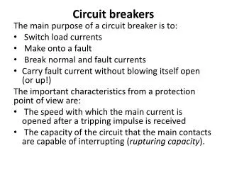
13.1 Introduction Concept of circuit breaker The basic construction of circuit breaker entails the separation of contacts in an insulating fluid. The circuit breakers are constructed using either a metal closure with two terminal bushings or an enclosure of insulating material with metal end caps. Insulation Insulating fluid Insulating fluid Metal Function of insulating fluid • - Extinguishment of the arc drawn between the contacts when the circuit breaker opens • Provision of adequate electrical insulation between the contacts and from each contact • to earth 1/34
13.1 Introduction Insulating fluid for circuit-breaker - Many insulating fluids are suitable for arc-extinction and the fluid chosen varies with the rating and type of circuit-breaker - The insulating fluid commonly used for circuit-breakers : Air at atmospheric pressure, Compressed air, oil (which produces hydrogen for arc extinction), ultra-high vacuum, Sulphur hexafluoride (SF6) Insulating fluid for ancillary equipment of circuit-breaker - Because arc interruption is not involved, the fluid can be chosen simply on its insulating merits. - Current transformers, Voltage transformers, Busbars - Arcton-12 (difluorodichloromethane) : Formation of carbon and chlorine during arcing 2/34
13.2 Modern switchgear practice Classification of circuit breakers - According to the insulating medium used for arc-extinction ~ 11kV : air-break type (using air at atmospheric pressure) or oil-break type 11kV ~ 66kV : mainly oil-breakers are in use 132kV ~ 275kV : oil-break type (small-oil or bulk-oil) and gas-blast type 400kV ~ 750kV : almost exclusively of the gas-blast type Extra high voltage gas-blast circuit breakers - Compressed air : up to 1000 lb/in2 - Operating pressure of SF6 : 200 lb/in2 - In any design, the gaseous insulation works in conjunction with solid insulation, and circuit breaker equipments differ basically in the form of the insulation from earth 3/34
13.2 Modern switchgear practice Two principal arrangements used for extra high voltage breakers Live-tank type Dead-tank type - Metal tank insulated from ground - Compressed gas is used - Tank is supported by a porcelain insulator - Several units can be used in series for the highest voltages - Tank being at ground potential - Contacts are insulated from the tank by compressed gas in parallel with solid insulation immersed in the gas 4/34
13.2 Modern switchgear practice Basic types in the extra high voltage gas blast breakers - Live or dead tank construction combined with either air or SF6 as extinguishing media - An evaluation of the respective merits of each type is complex because a large number of parameters must be taken into account (cost, size, maintenance, noise, extensibility, testing, insulation reliability etc.) 5/34
13.3 Gas-filled equipment 13.3.1. Live-tank circuit breakers Construction - A number of similar circuit breaking units are used in series per phase - Up to 12 breaks per phase are used for the highest breaking capacities at 400kV - Up to 24 breaks per phase are used for 750kV - The number of breaks is dictated by the limitation of testing station capacity rather than interrupting capacity possible per break - The tank is permanently charged with compressed gas and encloses two breaks connected in series, the tank being tied electrically to the mid-point potential between breaks - For 400kV, if twelve breaks are required, then two live tanks can be supported by a single porcelain insulator, making three support insulators in all phase 6/34
13.3 Gas-filled equipment 13.3.1. Live-tank circuit breakers - An insulating operating-rod and the ‘topping-up’ gas feed pipe are located inside the support porcelain - The insulating operating-rod and the ‘topping-up’ gas feed pipe are usually made in epoxy resin bonded glass fibre material - During a breaking operation, the blast valve is opened so that gas exhausts from the tank to atmosphere - The action of the high velocity gas flow through the nozzles brings rapid de-ionization of the arc column and extinction at a current zero 7/34
13.3 Gas-filled equipment 13.3.1. Live-tank circuit breakers Pollution - A major problem is the reduction in the flashover voltage external to the breaker due to the atmospheric pollution (industrial or coastal) - Non-graded insulation, is more vulnerable than graded insulation - When non-graded support insulators are used, sufficient creepage distance must be provided over the insulator to ground (2.5 ~ 3.5 cm/kVrms of line voltage) Voltage distribution - For a multi-break circuit breaker, the natural distribution of voltage between the breaks depends on the relative values of the capacitance between contacts and the capacitance to earth - For good grading the capacitance between contacts should be high and the capacitance to earth low - To obtain a more uniform voltage distribution, additional capacitance (or resistance) is usually added across each break 8/34
13.3 Gas-filled equipment 13.3.1. Live-tank circuit breakers 9/34
13.3 Gas-filled equipment 13.3.1. Live-tank circuit breakers Current transformers - Associated with circuit breakers are current transformers which transform the current in the high voltage line into a proportionate current, usually a lower one, at earth potential - The output from the transformer is used for metering and as a signal to open the circuit breaker if system conditions become abnormal - Current transformers associated with live tank breakers are of the separately mounted post type, unless the circuit breakers are accommodated inside a building in which case ring type current transformers can be mounted on the wall bushings feeding the building 10/34
13.3 Gas-filled equipment 13.3.2. Dead-tank circuit breakers Construction - ‘Dead tank’ breakers employ a single metal tank at earth potential - Bulk oil switchgear → gas blast market - When the breaker is tripped, the blast valve opens for several half-cycles and high- pressure gas flows down the blast pipes through interrupting nozzles into the main tank - Pressure in the main tank rises slightly and original conditions are restored by pumping gas from the main tank back into the high-pressure reservoir - Typical operating pressure : SF6, high pressure reservoir (200lb/in2) main tank (30lb/in2) 11/34
13.3 Gas-filled equipment 13.3.2. Dead-tank circuit breakers Advantage of a closed circuit gas system - Blast noise is considerably reduced because there is no exhaust to atmosphere - Exhaust gases ejected from gas blast circuit breakers may not be completely de-ionized and in any case can be at a high temperature, thereby reducing the flashover voltage between the circuit breaker and adjacent structures. Since there is no exhaust from breakers and to adjacent structures can be a minimum. This is particularly useful for indoor switching stations - Closed-circuit gas systems avoid ejecting large quantities of gas to atmosphere and the only gas fed to the circuit breaker is that needed to replace leaks. As all gas supplied to a circuit breaker must be dry, this reduction in consumption permits the use of more simple gas drying plant 12/34
13.3 Gas-filled equipment 13.3.2. Dead-tank circuit breakers Pollution - A major advantage of the dead tank construction is free from the hazard of atmospheric pollution - During the interruption, the gas exhausting into the main tank can carry particles formed by erosion of the contacts, nozzles and decomposition of the gas - This dust can be filtered and lied along insulating surfaces - Dust consists of metallic oxides or metallic fluoride which have good electric strength when dry - External to the breaker, there are two leakage path to earth at the bushings but as these are graded, the hazard are reduced 13/34
13.3 Gas-filled equipment 13.3.2. Dead-tank circuit breakers Pollution - With a multi break circuit breaker operating under conditions of severe pollution, a flashover to earth on the breaker itself would be much more serious if it occurred at the middle of the breaker, than at one of the terminals because only a fraction of the circuit breaker breaks is available to interrupt the fault of current. - Dead tank multi break circuit breakers have better insulation security between the terminals than do live tank breakers where the mid breaks bay be supported by exposed ungraded insulation - A dead tank breaker is more affected by loss of gas pressure but the risk of such a loss is negligible 14/34
13.3 Gas-filled equipment 13.3.2. Dead-tank circuit breakers Voltage distribution - The breaks are physically close together, hence the capacitance across of breaks can be made relatively high - The capacitance to earth is determined by the diameter of the tank, which from this aspect alone should be as great as possible - For breakers using an expensive gas such as SF6, the tank diameter must be small and dimensions are dictated by the clearance required to earth in a gas of high electric strength - For such breakers, the capacitance to earth is high and additional capacitors are provided across each break to improve the voltage distribution Current transformer - Ring type current transformers are fitted over the bushings on both sides of the breaker - This arrangement provides a saving in cost compared to post type transformers and eliminates the corresponding exposed insulation 15/34
13.3 Gas-filled equipment 13.3.3. Gas-filled current transformers Limitation of conventional insulation - At 132, 275 and 400kV, the conventional primary insulation for current transformers is oil-impregnated paper - The manufacturing problems associated with this insulation are formidable, particularly at voltages of 400kV and above - Large quantities of paper tape are applied to the primary conductor and lengthy processing under carefully controlled conditions is necessary to ensure dryness and full impregnation Most recent design - Focused on the use of electro-negative gases 16/34
13.3 Gas-filled equipment 13.3.3. Gas-filled current transformers Illustration of current transformer oil impregnate paper insulation type gaseous insulation type 17/34
13.3 Gas-filled equipment 13.3.3. Gas-filled current transformers Advantages of gas filled current transformer - Manufacturing process are more simple and shorter - No voids and less dielectric loss - Fire risk elimination - Weight saving - easier carriage of short circuit current than a hair pin shape conductor Disadvantages of gas filled current transformer - Sealing problems are more difficult - Stronger porcelain insulator is need to withstand the internal gas pressure - Voltage grading along the porcelain is more difficult 18/34
13.4 Practical gases for switchgear Gases for circuit breaker or for their ancillary equipment - Simple gases : air, oxygen, hydrogen, nitrogen, carbon dioxide - Electronegative gases : SF6, Arctons, nitriles Important preferred properties of gas - High electric strength - Thermal and chemical stability - Low liquefaction temperature - Non-inflammability - High thermal conductivity - Physiological inertness - Commercial availability at moderate cost - Arc-extinguishing ability 19/34
13.4 Practical gases for switchgear 13.4.1. Gases for circuit breakers Simple gases - Air is the cheapest and most widely used for circuit breaking - Hydrogen has a better arc-extinguishing ability and its thermal conductivity is seven times that of air, but its electric strength in fairly uniform fields is about half that of air Because of the risk of explosion, hydrogen-SF6 mixtures have been suggested - Nitrogen has a similar electric strength to air and offers no advantage in circuit breaking - The electric strength of carbon dioxide is similar to air and its arc-extinguishing properties are better than air at least at moderate current - Oxygen is a good extinguishing medium but is too active chemically, so it has been used in water circuit breakers where it is produced along with hydrogen during decomposition of the water by arc 20/34
13.4 Practical gases for switchgear 13.4.1. Gases for circuit breakers Electronegative gases - SF6 has outstanding arc-quenching properties and good electric strength - The fluorocarbon gases are unsuitable by virtue of their decomposition products and high dissociation temperatures - The nitriles have not been tested for use in circuit breakers → OF ALL THESE GASES, ONLY TWO, AIR AND SF6, ARE USED IN COMMERCIAL GAS BLAST CIRCUIT BREAKERS 21/34
13.4 Practical gases for switchgear 13.4.1. Gases for circuit breakers Air - The greater proportion of gas blast circuit breakers use compressed air for circuit interruption - The compressed air supply system is a vital part of an air blast circuit breaker and upon which the switchgear relies for mechanical operation, interrupting ability and internal insulation - The ensure adequate dryness of the air, moisture is removed by refrigeration, by drying agent, or by storing at several times the working pressure and then expanding to the working pressure for use in circuit breaker 22/34
13.4 Practical gases for switchgear 13.4.1. Gases for circuit breakers Sulphur hexafluoride (SF6) - Circuit breakers are assed by their ability to withstand the transient voltage that appears across the contacts immediately after current interruption (re-striking voltage) - SF6 is capable of interrupting a rate of rise of re-striking voltage of about four times that of air at the same pressure (200lb/in2) and the same current - If rate of mass through the interrupting nozzle is used as a common criterion, then SF6 has about twice the performance of air - SF6 has an electrical strength of about two or three times that of air at the same pressure, and at 2 atm its strength is comparable with that of transformer oil - Although SF6 is normally a vapour, it can be liquefied at moderate pressures and stored in steel cylinders in much the same manner as carbon dioxide 23/34
13.4 Practical gases for switchgear 13.4.1. Gases for circuit breakers Sulphur hexafluoride (SF6) - Metal fluorides which may be formed during the interruption of short circuit currents are removed from the circuit breaker tank by filtering the gas through activated alumina - During operation of the circuit breaker, the gaseous decomposition products which can be toxic in the presence of moisture, are removed using the activated alumina as an absorber - SF6 cannot be used much above 200lb/in2 unless the gas is heated to avoid liquefaction (Circuit breakers using SF6 at 200lb/in2 have heaters installed in the high pressure reservoir) - The breaking capacity of a circuit breaker is approximately proportional to the gas pressure; therefore it is possible for a compressed-air ‘break’ to have a higher interrupting capacity than an SF6 break at the expense of increased gas pressure 24/34
13.4 Practical gases for switchgear 13.4.1. Gases for circuit breakers Gas pressure – flashover voltage characteristics of insulation gases 25/34
13.4 Practical gases for switchgear 13.4.2. Gases for current transformers and busbars Gases filling current transformers and busbars - Arc-extinguishing properties can be forgotten, the problems become more simple 26/34
13.4 Practical gases for switchgear 13.4.2. Gases for current transformers and busbars Dilution of SF6 with other gases - Undiluted sulphur hexafluoride has been used at 30 ~ 40lb/in2 for gas insulated current transformer designed recently - Small additions of SF6 to nitrogen can produce electric strengths much greater than that of pure nitrogen - The breakdown value of 20% SF6, 80% N2 by pressure is approximately 80% breakdown value of pure SF6 - Work has been done on the dilution of SF6 both with nitrogen and with Arcton-12 (CF2Cl2) in order to save cost - The cost of pure SF6 is relatively small compared to that of the porcelain contains it - If suitable gas can be found having an electric strength twice that of SF6, then the diameter of the porcelain could be approximately halved - This could bring overall savings in cost 27/34
13.5 Design data Knowledge requirement to design the structural insulation - The voltages during service and during proving test - The voltage gradient at conductor surfaces and along solid insulating surfaces - Basic data on the electric strength of the gases and materials employed in the equipment Insulation levels for 400kV circuit breakers - Highest system voltage : 420kV - Impulse withstand to earth (1/50) : 1425kVp - Impulse withstand between phases and terminals of one phase (1/50) : 1640kVp - Power frequency (dry) 1min withstand : 680kV - Power frequency (dry) momentary withstand : 800kV - Power frequency (wet) 30s withstand : 630kV - Minimum visible corona voltage : 340kV - Minimum internal discharge voltage : 280kV - Minimum external axial creepage distance over porcelain insulators Outdoor circuit breaker to earth : 460in Indoor circuit breaker to earth : 400in Between terminals of one phase : 500in 28/34
13.5 Design data 13.5.1. Gas filled bushing Design parameters which require evaluation - The gas to be used and the operating pressure - The dimensions x, y, z, etc. - The effect of electrode materials, short circuit currents, moisture, dust, temperature, leaks, conditioning, and pollution Gases - Relatively low pressure : SF6 (45lb/in2), High pressure : Air - SF6 is used : porcelain weather-shield is sufficient to contain the gas - Air is used : necessary to provide a linear of epoxy-glass-fibre tube 29/34
13.5 Design data 13.5.1. Gas filled bushing Dimensions - Gap x : • determined from calculations of stress at the inner electrode and from data on the strength of gas • designed to withstand voltages greater than the external flashover voltage of the bushing 30/34
13.5 Design data 13.5.1. Gas filled bushing Dimensions - The length of the weather shield p : • determined by the 50 cycle and switching surge performance of porcelain and polluted conditions (Typically 132kV porcelain of length p is about 65in) - The total creepage distance z : • between 1.0 ~ 1.15in/kV of system line voltage for operation (ex. 132 ~ 152 in for a 132kV system) - The length and position of the earthed cylindrical screens (h1, h2) • determined by experiment : h1 and the external diameter of the bushing are sufficient to reduce the stress in the air ate the surface of the porcelain to less than 15kVp/cm h2 is chosen to give favorable stressing along the length y of lower insulating tube which is in compressed gas 31/34
13.5 Design data 13.5.1. Gas filled bushing Design data for insulated members in compressed gases - Right cylindrical insulating members in uniform field gap - The spacer efficiencies (ratio of flashover voltage to gas breakdown strength) up to 90% can be achieved at the lower pressures(10 ~ 30lb/in2) - In general, it is found for spacers immersed in SF6 and N2 at pressures up to 45lb/in2 in uniform field that, • cylindrical spacers have a higher flashover voltage than corrugated spacers • The surface finish of the spacer material should be as smooth as possible and the spacer electrode contact as intimate as possible for the highest spacer efficiencies A spacer material of low permittivity may also be an advantage • Spacer efficiency often decrease with increase in gas pressure and this effect is more marked with SF6 than with N2 32/34
13.5 Design data 13.5.1. Gas filled bushing 33/34
13.5 Design data 13.5.2. Future requirement - Equipment such as circuit breakers and current transformers is designed to be free from internal discharge at 15% above the normal phase to neutral system voltage - The design of equipment for 400 and 750kV requires data on the breakdown of gaps and gas/solid interfaces of a metre in length at gas pressures up to 100 atm - Data of this kind require the use of very high test voltages and the construction of large test rings - Both these requirements are costly and work of this type is usually only fostered in industrial laboratories - A reliable technique for translating breakdown data from small models to full sized equipment would be of obvious value 34/34